NGFW device dual-active egress gateway typical configuration
- 0关注
- 0收藏 2431浏览

Network Topology
As shown in Figure 1, two F1050s form an IRF. Intranet users aggregate HASH through the firewall"s downlink and are distributed to two devices. The firewall is routed to the telecommunications network and China Unicom network through link load balancing technology. Configure on F1050 Link aggregation is locally preferred, and local forwarding traffic is prioritized from the device to avoid horizontal traffic. Because there are asymmetric scenarios, you need to configure the session hot backup function.
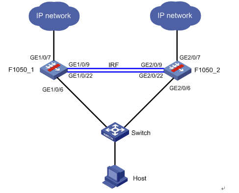
• Establish IRF between two F1050s.
• In order to prevent the IRF from splitting due to an IRF link failure, two IRFs with conflicting configurations are generated on the network, and the MAD detection function needs to be enabled. Detect GE1/0/4 of F1050_1 and GE2/0/4 of F1050_2 BFD MAD.
• Configure GE1/0/6 of F1050_1 and GE2/0/6 of F1050_2 as Layer 3 aggregation ports. GE1/0/7 of F1050_1 is configured as a telecom network outgoing interface and added to aggregation group 2, and GE2/0/7 of F1050_2 is configured as a Unicom network outgoing interface, and it is also added to aggregation group 3.
• Configure link load balancing on the firewall to load-share intranet traffic between the two links.
Configuration Steps
Configuration Notes:
Pay attention to the configuration sequence when configuring the stack for the F1050. After saving the configuration, activate the stack port configuration.
F1050 IRF
# # IRF configuration (Two F1050s can be connected through multiple IRF ports. Take GE1/0/9~GE2/0/9 and GE1/0/22~GE2/0/22 as examples below)
F1050_1 configuration
# Configure member number and priority
[F1050_1] irf member 1 priority 32
# Configure F1050_1, configure IRF port 1/1, bind it to physical ports GE1/0/9 and GE1/0/22, save the configuration, and activate the configuration under the IRF port.
[F1050_1] interface GigabitEthernet 1/0/9
[F1050_1-GigabitEthernet1/0/9] shutdown
[F1050_1-GigabitEthernet1/0/9] quit
[F1050_1] interface GigabitEthernet 1/0/22
[F1050_1-GigabitEthernet1/0/22] shutdown
[F1050_1-GigabitEthernet1/0/22] quit
[F1050_1] irf-port 1/1
[F1050_1-irf-port1/1] port group interface GigabitEthernet 1/0/9
[F1050_1-irf-port1/1] port group interface GigabitEthernet 1/0/22
[1050_1-irf-port1/1] quit
[F1050_1] interface GigabitEthernet 1/0/9
[F1050_1-GigabitEthernet1/0/9] undo shutdown
[F1050_1-GigabitEthernet1/0/9] quit
[F1050_1] interface GigabitEthernet 1/0/22
[F1050_1-GigabitEthernet1/0/22] undo shutdown
[F1050_1-GigabitEthernet1/0/22] quit
[F1050_1] save
[F1050_1] irf-port-configuration active
(1) Configuration of F1050_2
# Configure member number
[F1050_2] irf member 1 renumber 2
Warning: Renumbering the member ID may result in configuration change or loss. Continue? [Y/N]:y
[F1050_2] quit
# F1050_2 After restarting, log in to the device and set the IRF priority.
[F1050_2] irf member 2 priority 1
# Configure IRF port 2/2 and bind it to physical ports GE2/0/9 and GE2/0/22, save the configuration, and activate the configuration under the IRF port.
[F1050_2] interface GigabitEthernet 2/0/9
[F1050_2-GigabitEthernet2/0/9] shutdown
[F1050_2-GigabitEthernet2/0/9] quit
[F1050_2] interface GigabitEthernet 2/0/22
[F1050_2-GigabitEthernet2/0/22] shutdown
[F1050_2-GigabitEthernet2/0/22] quit
[F1050_2] irf-port 2/2
[F1050_2-irf-port2/2] port group interface GigabitEthernet 2/0/9
[F1050_2-irf-port2/2] port group interface GigabitEthernet 2/0/22
[F1050_2-irf-port2/2] quit
[F1050_2] interface GigabitEthernet 2/0/9
[F1050_2-GigabitEthernet2/0/9] undo shutdown
[F1050_2-GigabitEthernet2/0/9] quit
[F1050_2] interface GigabitEthernet 2/0/22
[F1050_2-GigabitEthernet2/0/22] undo shutdown
[F1050_2-GigabitEthernet2/0/22] quit
[F1050_2] save
[F1050_2] irf-port-configuration active
F1050 aggregate interface configuration
# F1050 is configured with a three-layer aggregation port in the downstream to split the downstream application traffic to two devices.
# Enable the aggregation acceleration function, which needs to be configured in dual main mode.
[F1050_1] link-aggregation global forwarding-acceleration enable
# GE1/0/6 of F1050_1 and GE2/0/6 of F1050_2 form the aggregation port RAGG1.
[F1050_1] interface Route-Aggregation 1
[F1050_1-Route-Aggregation1] quit
[F1050_1] interface GigabitEthernet 1/0/6
[F1050_1-GigabitEthernet1/0/6] port link-aggregation group 1
[F1050_1-GigabitEthernet1/0/6] quit
[F1050_1] interface GigabitEthernet 2/0/6
[F1050_1-GigabitEthernet2/0/6] port link-aggregation group 1
[F1050_1-GigabitEthernet2/0/6] quit
# Configure the IP address of the aggregation port BAGG1.
[F1050_1] interface Route-Aggregation 1
[F1050_1-Route-Aggregation1] ip address 192.168.1.254 24
[F1050_1-Route-Aggregation1] quit
# Add the aggregation port to the security zone trust.
[F1050_1] security-zone name trust
[F1050_1-security-zone-Trust] import interface Route-Aggregation 1
[F1050_1-security-zone-Trust] quit
F1050 link load balancing configuration
# Create link group lg1 of isp1 where Link1 and Link2 are located, and configure the algorithm to rotate
[F1050_1] loadbalance link-group lg1
[F1050_1-lb-lgroup-lg1] predictor round-robin
[F1050_1-lb-lgroup-lg1] transparent enable
[F1050_1-lb-lgroup-lg1] quit
# Create links Link1 and Link2 and belong to link group lg1.
[F1050_1] loadbalance link link-1
[F1050_1-lb-link-link-1] router ip 10.152.2.254
//
[F1050_1-lb-link-link-1] link-group lg1
[F1050_1-lb-link-link-1] quit
[F1050_1] loadbalance link link-2
[F1050_1-lb-link-link-2] router ip 10.152.3.254
//
[F1050_1-lb-link-link-2] link-group lg1
[F1050_1-lb-link-link-2] quit
# Create a NAT address pool address globally.
[F1050_1] nat outbound address-group 1
[F1050_1-address-group-1] address 10.153.1.10 10.153.1.10
[F1050_1-address-group-1] quit
[F1050_1] nat outbound address-group 2
[F1050_1-address-group-1] address 10.154.1.10 10.154.1.10
[F1050_1-address-group-1] quit
# NAT outbound is enabled on the corresponding interfaces of link link-1 and link-2, referencing address pool addresses 1, 2 respectively
[F1050_1] interface Route-Aggregation 2
[F1050_1-Route-Aggregation2] nat outbound address-group 1
[F1050_1-Route-Aggregation2] quit
[F1050_1] interface Route-Aggregation 3
[F1050_1-Route-Aggregation3] nat outbound address-group 2
[F1050_1-Route-Aggregation2] quit
# Enable slot1 NAT port load sharing function globally. In the load sharing scenario of dual-system hot backup, after the NAT port load sharing function is enabled, the two devices each get half of the port block resources, so that the same private network IP address can exclusively occupy certain port resources on different member devices, avoiding port allocation conflict. When it is not turned on, there may be multiple private network addresses that use the same port after NAT translation, causing session conflicts.
[F1050_1] nat port-load-balance enable slot 1
# Create a traffic classification class-1, based on the application group app-1 and ACL 3001 to match the HTTP traffic whose source IP is the IP address of the 192.168.0.0/16 network segment.。
[F1050_1] acl advanced 3001
[F1050_1-acl-ipv4-adv-3001] rule permit ip source 192.168.0.0 0.0.255.255
[F1050_1-acl-ipv4-adv-3001] quit
[F1050_1] app-group app-1
[F1050_1-app-group-app-1] include application http
[F1050_1-app-group-app-1] quit
[F1050_1] loadbalance class class-1 type link-generic
[F1050_1-lbc-link-generic-class-1] match acl 3001
[F1050_1-lbc-link-generic-class-1] match app-group app-1
[F1050_1-lbc-link-generic-class-1] quit
# Create the flow action action-1 to bind the link group lg1.
[F1050_1] loadbalance action action-1 type link-generic
[F1050_1-lba-link-generic-action-1] link-group lg1
[F1050_1-lba-link-generic-action-1] quit
# Create an LB policy to bind flow classification and flow actions.
[F1050_1] loadbalance policy policy-1 type link-generic
[F1050_1-lbp-link-generic-policy-1] class class-1 action action-1
[F1050_1-lbp-link-generic-policy-1] quit
# Create a virtual service VS as an all-zero network segment, bind the LB policy, and enable the virtual service. Turn on hot session backup.
[F1050_1] virtual-server vs type link-ip
[F1050_1-vs-link-ip-vs] virtual ip address 0.0.0.0 0
[F1050_1-vs-link-ip-vs] lb-policy policy-1
[F1050_1-vs-link-ip-vs] service enable
# Turn on session backup. This item is required to ensure that asymmetric traffic can be forwarded.
[F1050_1-vs-link-ip-vs] connection-sync enable
# This item is optional and can be configured when there are persistent entries.
[F1050_1-vs-link-ip-vs] sticky-sync enable
[F1050_1-vs-link-ip-vs] quit
F1050 BFD MAD
[F1050_1] vlan 30
[F1050_1] interface GigabitEthernet 1/0/4
[F1050_1-GigabitEthernet1/0/4] port link-mode bridge
[F1050_1-GigabitEthernet1/0/4] port access vlan 30
[F1050_1-GigabitEthernet1/0/4] quit
[F1050_1] interface GigabitEthernet 2/0/4
[F1050_1-GigabitEthernet2/0/4] port link-mode bridge
[F1050_1-GigabitEthernet2/0/4] port access vlan 30
[F1050_1-GigabitEthernet2/0/4] quit
[F1050_1] interface Vlan-interface 30
[1050-1-Vlan-interface30] mad ip address 192.168.30.1 255.255.255.0 member 1
[1050-1-Vlan-interface30] mad ip address 192.168.30.2 255.255.255.0 member 2
[1050-1-Vlan-interface30] mad bfd enable
[F1050_1-Vlan-interface30] quit
[F1050_1] security-zone name trust
[F1050_1-security-zone-Trust] import interface Vlan-interface30
[F1050_1-security-zone-Trust] quit
Outbound interface, security zone and other configuration
(2) Configure IP addresses for GE1/0/7 and GE2/0/7 and join the security zone untrust
[F1050_1] interface Route-Aggregation 2
[F1050_1-Route-Aggregation2] ip address 10.152.2.1 24
[F1050_1-Route-Aggregation2] quit
[F1050_1] interface GigabitEthernet 1/0/7
[F1050_1-GigabitEthernet1/0/7] port link-aggregation group 2
[F1050_1-GigabitEthernet1/0/7] quit
[F1050_1] interface Route-Aggregation 3
[F1050_1-Route-Aggregation3] ip address 10.152.3.1 24
[F1050_1-Route-Aggregation3] quit
[F1050_1] interface GigabitEthernet 2/0/7
[F1050_1-GigabitEthernet2/0/7] port link-aggregation group 3
[F1050_1-GigabitEthernet2/0/7] quit
[F1050_1] security-zone name untrust
[F1050_1-security-zone-Untrust] import interface Route-Aggregation 2
[F1050_1-security-zone-Untrust] import interface Route-Aggregation 3
[F1050_1-security-zone-Untrust] quit
(3)
[F1050_1] acl advanced 3000
[F1050_1-acl-ipv4-adv-3000] rule permit ip
[F1050_1-acl-ipv4-adv-3000] quit
[F1050_1] zone-pair security source trust destination untrust
[F1050_1-zone-pair-security-Trust-Untrust] packet-filter 3000
[F1050_1-zone-pair-security-Trust-Untrust] quit
[F1050_1] zone-pair security source trust destination local
[F1050_1-zone-pair-security-Trust-Local] packet-filter 3000
[F1050_1-zone-pair-security-Trust-Local] quit
[F1050_1] zone-pair security source untrust destination local
[F1050_1-zone-pair-security-Untrust-Local] packet-filter 3000
[F1050_1-zone-pair-security-Untrust-Local] quit
[F1050_1] zone-pair security source untrust destination trust
[F1050_1-zone-pair-security-Untrust-Trust] packet-filter 3000
[F1050_1-zone-pair-security-Untrust-Trust] quit
[F1050_1] zone-pair security source local destination trust
[F1050_1-zone-pair-security-Local-Trust] packet-filter 3000
[F1050_1-zone-pair-security-Local-Trust] quit
[F1050_1] zone-pair security source local destination untrust
[F1050_1-zone-pair-security-Local-Untrust] packet-filter 3000
[F1050_1-zone-pair-security-Local-Untrust] quit
(4)
[F1050_1] link-aggregation load-sharing mode local-first
(5)
[F1050_1] session synchronization enable
[F1050_1] session synchronization dns http
Key Configuration
Verify configuration
(1)
MemberID Role Priority CPU-Mac Description
*1 Master 32 50da-00eb-7ba1 ---
+2 Standby 1 50da-00eb-7bd5 ---
--------------------------------------------------
* indicates the device is the master.
+ indicates the device through which the user logs in.
The bridge MAC of the IRF is: 50da-00eb-7b9f
Auto upgrade : yes
Mac persistent : 6 min
Domain ID : 0
GE1/0/6 S 32768 1
GE2/0/6 S 32768 1
(2)
Loadsharing Type: Shar -- Loadsharing, NonS -- Non-Loadsharing
Port Status: S -- Selected, U -- Unselected, I -- Individual
Flags: A -- LACP_Activity, B -- LACP_Timeout, C -- Aggregation,
D -- Synchronization, E -- Collecting, F -- Distributing,
G -- Defaulted, H -- Expired
Aggregate Interface: Route-Aggregation1
Aggregation Mode: Static
Loadsharing Type: Shar
Port Status Priority Oper-Key
--------------------------------------------------------------------------------
GE1/0/6 S 32768 1
GE2/0/6 S 32768 1
(3)
Virtual server: vs
Description:
Type: LINK-IP
State: Active
VPN instance:
Virtual IPv4 address: 0.0.0.0/0
Virtual IPv6 address: --
Port: 0
Primary link group:
Backup link group:
Sticky:
LB policy: policy-1
LB limit-policy:
Connection limit: --
Rate limit:
Connections: --
Bandwidth: --
Inbound bandwidth: --
Outbound bandwidth: --
Connection synchronization: Enabled
Sticky synchronization: Disabled
Bandwidth busy protection: Disabled
Interface bandwidth statistics: Disabled
Route advertisement: Disabled
No comments
Add Comments:
✖
案例意见反馈


亲~登录后才可以操作哦!
确定你的邮箱还未认证,请认证邮箱或绑定手机后进行当前操作