客户采购两台M9000设备,每台M9000上部署有1块防火墙业务单板和1板接口板。为实现两台M9000的主备关系组网,需要配置冗余口、冗余组、备份组等。本案例主要描述和介绍前述三者的关键配置项,其它配置功能简略。本配置案例在M9000 CMW710-R9115版本中测试验证。
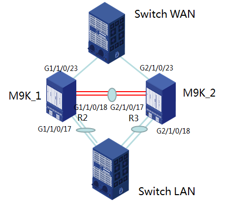
如图所示,两台M9000各有一个物理口与上行交换机互联,各有一个聚合口与下行交换机互联,M9000之间有IRF链路和MAD链路等。
两个上行Ge口作为成员口形成一个冗余口,两个下行聚合口作为成员口形成一个冗余口;两块防火墙板形成备份组;冗余口和备份组作为成员加入冗余组。
1、两台M9000配置IRF II、BFD MAD、业务端口、管理相关等基础配置。(略)
2、形成IRF组网后,关闭本地转发优先。
[H3C]undo link-aggregation load-sharing mode local-first
3、配置备份组
要求两台M9000统一以1号框为主,2号框为备。两块防火墙板卡安装在7号槽位,因此配置组的关键配置如下:
[H3C]failover group 0
bind chassis 1 slot 7 cpu 1 primary
bind chassis 2 slot 7 cpu 1 secondary
4、配置冗余口
上行两个Ge端口形成冗余口,成员端口为物理口,1号框的端口为主端口,2号框的端口为备端口。对端上联设备IP地址为172.16.10.1/24。
[H3C]interface Reth1
ip address 172.16.10.2 255.255.255.0
member interface GigabitEthernet1/1/0/23 priority 90
member interface GigabitEthernet2/1/0/23 priority 10
下行两个三层聚合端口形成冗余口,成员端口为聚合口,1号框的端口为主端口,2号框的端口为备端口。对端下联设备IP地址为172.16.20.1/24。
[H3C]interface Reth2
ip address 172.16.20.2 255.255.255.0
member interface Route-Aggregation2 priority 90
member interface Route-Aggregation3 priority 10
5、聚合口最小选中端口配置
为实现当聚合口中的某个成员端口出现故障后冗余组可以正常切换,需要为聚合端口配置最小选中成员口特性,实现聚合口不借助Track监控,利用自身特性与物理端口联动。在本例中,两个聚合口都为双Ge口,因此最小选中成员口数量应配置为2。
[H3C] interface Route-Aggregation2
link-aggregation selected-port minimum 2
[H3C] interface Route-Aggregation3
link-aggregation selected-port minimum 2
6、配置Track项
配置Track关联,用于冗余组对成员的状态监控和主备切换。
关于防火墙板的Track项,应该直接关联Blade口物理状态。
[H3C]track 1 interface Blade1/7/0/1 physical
[H3C]track 2 interface Blade2/7/0/1 physical
[H3C]track 11 interface GigabitEthernet1/1/0/23 physical
[H3C]track 12 interface Route-Aggregation2 physical
[H3C]track 21 interface GigabitEthernet2/1/0/23 physical
[H3C]track 22 interface Route-Aggregation3 physical
7、配置冗余组
冗余组为全局概念,在系统视图下配置。冗余组的成员为冗余口和备份组。冗余组包含两个Node节点,默认优先级相同,以1号为主,2号为备。配置时要注意将主用1号框和节点1绑定,将备用2号框和节点2绑定
[H3C]redundancy group 0
member interface Reth1
member interface Reth2
member failover group 0
node 1
bind chassis 1
track 1
track 11 interface GigabitEthernet1/1/0/23
track 12 interface Route-Aggregation2
node 2
bind chassis 2
track 2
track 21 interface GigabitEthernet2/1/0/23
track 22 interface Route-Aggregation3
8、功能验证
当两个机框所有的业务端口、板卡工作状态正常时,备份组、冗余口、冗余组状态如下:
[H3C]display failover group 0
Stateful failover group information:
ID Name Primary Secondary Active Status
0 0 1/7.1 2/7.1 Primary
[H3C]display reth interface Reth 1
Reth1 :
Redundancy group : 0
Member Physical status Forwarding status Presence status
GE1/1/0/23 UP Active Normal
GE2/1/0/23 UP Inactive Normal
[H3C]display reth interface Reth 2
Reth2 :
Redundancy group : 0
Member Physical status Forwarding status Presence status
RAGG2 UP Active Normal
RAGG3 UP Inactive Normal
[H3C]display redundancy group 0
Redundancy group 0 (ID 3):
Node ID Chassis Priority Status Track weight
1 Chassis1 1 Primary 255
2 Chassis2 1 Secondary 255
Preempt delay time remained : 0 min
Preempt delay timer setting : 1 min
Remaining hold-down time : 0 sec
Hold-down timer setting : 1 sec
Manual switchover requeset : No
Member interfaces:
Reth2 Reth1
Member failover groups:
0
Node 1:
Track info:
Track Status Reduced weight Interface
1 Positive 255 N/A
11 Positive 255 GE1/1/0/23
12 Positive 255 RAGG2
Node 2:
Track info:
Track Status Reduced weight Interface
2 Positive 255 N/A
21 Positive 255 GE2/1/0/23
22 Positive 255 RAGG3
当手工将Ge1/1/0/17端口关闭后,M9000备份组、冗余口、冗余组状态如下:
[H3C]display failover group 0
Stateful failover group information:
ID Name Primary Secondary Active Status
0 0 1/7.1 2/7.1 Secondary
[H3C]display reth interface Reth 1
Reth1 :
Redundancy group : 0
Member Physical status Forwarding status Presence status
GE1/1/0/23 DOWN(redundancy down) Inactive Normal
GE2/1/0/23 UP Active Normal
[H3C]display reth interface Reth 2
Reth2 :
Redundancy group : 0
Member Physical status Forwarding status Presence status
RAGG2 DOWN Inactive Normal
RAGG3 UP Active Normal
[H3C]display redundancy group 0
Redundancy group 0 (ID 3):
Node ID Chassis Priority Status Track weight
1 Chassis1 1 Secondary -255
2 Chassis2 1 Primary 255
Preempt delay time remained : 0 min
Preempt delay timer setting : 1 min
Remaining hold-down time : 0 sec
Hold-down timer setting : 1 sec
Manual switchover requeset : No
Member interfaces:
Reth2 Reth1
Member failover groups:
0
Node 1:
Track info:
Track Status Reduced weight Interface
1 Positive 255 N/A
11 Negative 255 GE1/1/0/23
12 Negative 255 RAGG2(Fault)
Node 2:
Track info:
Track Status Reduced weight Interface
2 Positive 255 N/A
21 Positive 255 GE2/1/0/23
22 Positive 255 RAGG3
1、在规划冗余口、冗余组、备份组主备关系时,务必保持三者主备关系一致,建议全部以1号框为主、2号框为备。
2、在实施冗余口配置时,如果添加的成员端口为物理口,而全局和冗余组Node节点下都应Track物理口状态;如果添加的成员端口为聚合口,而全局和冗余组Node节点下都应Track聚合口状态。
3、系统全局模式下配置Track项时,必须携带“physical”参数。
4、冗余组Node节点下配置Track项时,冗余口成员端口的Track项目必须携带关联口参数,即配置命令为系统全局模式下省略“physical”参数;防火墙板Track项直接引用全局模式下的Track项目即可,不必携带blade板参数。
5、冗余组Node节点下绑定的机框号和关联的Track端口必须一致,不可以配置Node1下绑定1号框但关联2号框端口Track项。
6、冗余口的成员口和相应Track项的关联口必须一致,不可以配置成员口为聚合口但关联的Track项为聚合口的成员端口,否则当发生端口Down事件时,物理口Down、聚合口Down、冗余口及冗余组Down等多个事件会造成最终状态混乱,使主备备份状态不符合预期。
7、支持将聚合子接口作为成员加入冗余口,此时需注意在配置Track项时,在系统全局和冗余组Node下检视的端口也应为聚合子接口。
8、注意系统默认或用户自定义的各个计时器,例如冗余组各检视项状态恢复后,缺省的倒回延迟时间为1分钟,因此当故障点恢复后,系统要等待一分钟后才能恢复正常的主备关系。