m-lag
- 0关注
- 1收藏,2663浏览

问题描述:
m-lag技术
组网及组网描述:
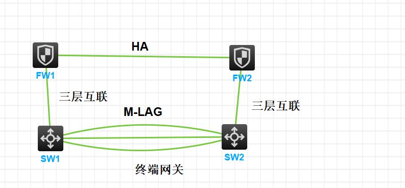
防火墙为出口做HA,和核心交换机三层互联,交换机做M-lag,核心交换机为下联终端业务网关,有没有口字型m-lag的配置案例,找了没找到,有大佬知道的发下谢谢
- 2023-07-03提问
- 举报
-
(0)
最佳答案


您好,参考
1.22.2 M-LAG三层转发配置举例
1. 组网需求
· 由于用户对于业务的可靠性要求很高,如果Device C和接入设备(Device A和Device B)之间配置链路聚合只能保证链路级的可靠性,接入设备发生故障时则会导致业务中断。这时用户可以采用M-LAG技术,正常工作时链路进行负载分担且任何一台设备故障对业务均没有影响,保证业务的高可靠性。
· 配置Device A和Device B的三层以太网接口Ten-GigabitEthernet1/0/5为保留接口,在该三层以太网口上搭建Keepalive链路,保证Keepalive报文能够正常传输。
· VLAN 100内主机的缺省网关为10.1.1.100/24,VLAN 101内主机的缺省网关为20.1.1.100/24。Device A和Device B同时属于虚拟IP地址为10.1.1.100/24的备份组1和虚拟IP地址为20.1.1.100/24的备份组2。在备份组1和备份组2中Device A的优先级高于Device B。
2. 组网图
图1-13 M-LAG三层转发配置组网图

3. 配置步骤
(1) 配置Device A
# 系统配置。
<DeviceA> system-view
[DeviceA] m-lag system-mac 1-1-1
[DeviceA] m-lag system-number 1
[DeviceA] m-lag system-priority 123
# 配置Keepalive报文的目的IP地址和源IP地址。
[DeviceA] m-lag keepalive ip destination 1.1.1.2 source 1.1.1.1
# 配置端口Ten-GigabitEthernet1/0/5工作在三层模式,并配置IP地址为Keepalive报文的源IP地址。
[DeviceA] interface ten-gigabitethernet 1/0/5
[DeviceA-Ten-GigabitEthernet1/0/5] port link-mode route
[DeviceA-Ten-GigabitEthernet1/0/5] ip address 1.1.1.1 24
[DeviceA-Ten-GigabitEthernet1/0/5] quit
# 配置Keepalive链路接口为M-LAG保留接口。
[DeviceA] m-lag mad exclude interface ten-gigabitethernet 1/0/5
# 创建动态二层聚合接口125。
[DeviceA] interface bridge-aggregation 125
[DeviceA-Bridge-Aggregation125] link-aggregation mode dynamic
[DeviceA-Bridge-Aggregation125] quit
# 分别将端口Ten-GigabitEthernet1/0/3和Ten-GigabitEthernet1/0/4加入到聚合组125中。
[DeviceA] interface ten-gigabitethernet 1/0/3
[DeviceA-Ten-GigabitEthernet1/0/3] port link-aggregation group 125
[DeviceA-Ten-GigabitEthernet1/0/3] quit
[DeviceA] interface ten-gigabitethernet 1/0/4
[DeviceA-Ten-GigabitEthernet1/0/4] port link-aggregation group 125
[DeviceA-Ten-GigabitEthernet1/0/4] quit
# 配置二层聚合接口125为peer-link接口。
[DeviceA] interface bridge-aggregation 125
[DeviceA-Bridge-Aggregation125] port m-lag peer-link 1
[DeviceA-Bridge-Aggregation125] undo mac-address static source-check enable
[DeviceA-Bridge-Aggregation125] quit
# 创建动态二层聚合接口100,并配置该接口为M-LAG接口1。
[DeviceA] interface bridge-aggregation 100
[DeviceA-Bridge-Aggregation100] link-aggregation mode dynamic
[DeviceA-Bridge-Aggregation100] port m-lag group 1
[DeviceA-Bridge-Aggregation100] quit
# 将端口Ten-GigabitEthernet1/0/1加入到聚合组100中。
[DeviceA] interface ten-gigabitethernet 1/0/1
[DeviceA-Ten-GigabitEthernet1/0/1] port link-aggregation group 100
[DeviceA-Ten-GigabitEthernet1/0/1] quit
# 创建动态二层聚合接口101,并配置该接口为M-LAG接口2。
[DeviceA] interface bridge-aggregation 101
[DeviceA-Bridge-Aggregation101] link-aggregation mode dynamic
[DeviceA-Bridge-Aggregation101] port m-lag group 2
[DeviceA-Bridge-Aggregation101] quit
# 将端口Ten-GigabitEthernet1/0/2加入到聚合组101中。
[DeviceA] interface ten-gigabitethernet 1/0/2
[DeviceA-Ten-GigabitEthernet1/0/2] port link-aggregation group 101
[DeviceA-Ten-GigabitEthernet1/0/2] quit
# 创建VLAN 100和101。
[DeviceA] vlan 100
[DeviceA-vlan100] quit
[DeviceA] vlan 101
[DeviceA-vlan101] quit
# 配置二层聚合接口100为Trunk端口,并允许VLAN 100的报文通过。
[DeviceA] interface bridge-aggregation 100
[DeviceA-Bridge-Aggregation100] port link-type trunk
[DeviceA-Bridge-Aggregation100] port trunk permit vlan 100
[DeviceA-Bridge-Aggregation100] quit
# 配置二层聚合接口101为Trunk端口,并允许VLAN 101的报文通过。
[DeviceA] interface bridge-aggregation 101
[DeviceA-Bridge-Aggregation101] port link-type trunk
[DeviceA-Bridge-Aggregation101] port trunk permit vlan 101
[DeviceA-Bridge-Aggregation101] quit
# 创建接口Vlan-interface100和Vlan-interface101,并配置其IP地址。
[DeviceA] interface vlan-interface 100
[DeviceA-vlan-interface100] ip address 10.1.1.1 24
[DeviceA-vlan-interface100] quit
[DeviceA] interface vlan-interface 101
[DeviceA-vlan-interface101] ip address 20.1.1.1 24
[DeviceA-vlan-interface101] quit
# 配置Vlan-interface100和Vlan-interface101接口为M-LAG保留接口。
[DeviceA] m-lag mad exclude interface vlan-interface 100
[DeviceA] m-lag mad exclude interface vlan-interface 101
# 配置OSPF。
[DeviceA] ospf
[DeviceA-ospf-1] import-route direct
[DeviceA-ospf-1] area 0
[DeviceA-ospf-1-area-0.0.0.0] network 10.1.1.0 0.0.0.255
[DeviceA-ospf-1-area-0.0.0.0] network 20.1.1.0 0.0.0.255
[DeviceA-ospf-1-area-0.0.0.0] quit
[DeviceA-ospf-1] quit
# 为接口Vlan-interface100创建备份组1,并配置备份组1的虚拟IP地址为10.1.1.100。
[DeviceA] interface vlan-interface 100
[DeviceA-Vlan-interface100] vrrp vrid 1 virtual-ip 10.1.1.100
# 设置Device A在备份组1中的优先级为200,以保证Device A成为Master负责转发流量。
[DeviceA-Vlan-interface100] vrrp vrid 1 priority 200
[DeviceA-Vlan-interface100] quit
# 为接口Vlan-interface101创建备份组2,并配置备份组2的虚拟IP地址为20.1.1.100。
[DeviceA] interface vlan-interface 101
[DeviceA-Vlan-interface101] vrrp vrid 2 virtual-ip 20.1.1.100
# 设置Device A在备份组2中的优先级为200,以保证Device A成为Master负责转发流量。
[DeviceA-Vlan-interface101] vrrp vrid 2 priority 200
[DeviceA-Vlan-interface101] quit
(2) 配置Device B
# 系统配置。
<DeviceB> system-view
[DeviceB] m-lag system-mac 1-1-1
[DeviceB] m-lag system-number 2
[DeviceB] m-lag system-priority 123
# 配置Keepalive报文的目的IP地址和源IP地址。
[DeviceB] m-lag keepalive ip destination 1.1.1.1 source 1.1.1.2
# 配置端口Ten-GigabitEthernet1/0/5工作在三层模式,并配置IP地址为Keepalive报文的源IP地址。
[DeviceB] interface ten-gigabitethernet 1/0/5
[DeviceB-Ten-GigabitEthernet1/0/5] port link-mode route
[DeviceB-Ten-GigabitEthernet1/0/5] ip address 1.1.1.2 24
[DeviceB-Ten-GigabitEthernet1/0/5] quit
# 配置Keepalive链路接口为M-LAG保留接口。
[DeviceB] m-lag mad exclude interface ten-gigabitethernet 1/0/5
# 创建动态二层聚合接口125。
[DeviceB] interface bridge-aggregation 125
[DeviceB-Bridge-Aggregation125] link-aggregation mode dynamic
[DeviceB-Bridge-Aggregation125] quit
# 分别将端口Ten-GigabitEthernet1/0/3和Ten-GigabitEthernet1/0/4加入到聚合组125中。
[DeviceB] interface ten-gigabitethernet 1/0/3
[DeviceB-Ten-GigabitEthernet1/0/3] port link-aggregation group 125
[DeviceB-Ten-GigabitEthernet1/0/3] quit
[DeviceB] interface ten-gigabitethernet 1/0/4
[DeviceB-Ten-GigabitEthernet1/0/4] port link-aggregation group 125
[DeviceB-Ten-GigabitEthernet1/0/4] quit
# 配置二层聚合接口125为peer-link接口。
[DeviceB] interface bridge-aggregation 125
[DeviceB-Bridge-Aggregation125] port m-lag peer-link 1
[DeviceB-Bridge-Aggregation125] undo mac-address static source-check enable
[DeviceB-Bridge-Aggregation125] quit
# 创建动态二层聚合接口100,并配置该接口为M-LAG接口1。
[DeviceB] interface bridge-aggregation 100
[DeviceB-Bridge-Aggregation100] link-aggregation mode dynamic
[DeviceB-Bridge-Aggregation100] port m-lag group 1
[DeviceB-Bridge-Aggregation100] quit
# 将端口Ten-GigabitEthernet1/0/1加入到聚合组100中。
[DeviceB] interface ten-gigabitethernet 1/0/1
[DeviceB-Ten-GigabitEthernet1/0/1] port link-aggregation group 100
[DeviceB-Ten-GigabitEthernet1/0/1] quit
# 创建动态二层聚合接口101,并配置该接口为M-LAG接口2。
[DeviceB] interface bridge-aggregation 101
[DeviceB-Bridge-Aggregation101] link-aggregation mode dynamic
[DeviceB-Bridge-Aggregation101] port m-lag group 2
[DeviceB-Bridge-Aggregation101] quit
# 将端口Ten-GigabitEthernet1/0/2加入到聚合组101中。
[DeviceB] interface ten-gigabitethernet 1/0/2
[DeviceB-Ten-GigabitEthernet1/0/2] port link-aggregation group 101
[DeviceB-Ten-GigabitEthernet1/0/2] quit
# 创建VLAN 100和101。
[DeviceB] vlan 100
[DeviceB-vlan100] quit
[DeviceB] vlan 101
[DeviceB-vlan101] quit
# 配置二层聚合接口100为Trunk端口,并允许VLAN 100的报文通过。
[DeviceB] interface bridge-aggregation 100
[DeviceB-Bridge-Aggregation100] port link-type trunk
[DeviceB-Bridge-Aggregation100] port trunk permit vlan 100
[DeviceB-Bridge-Aggregation100] quit
# 配置二层聚合接口101为Trunk端口,并允许VLAN 101的报文通过。
[DeviceB] interface bridge-aggregation 101
[DeviceB-Bridge-Aggregation101] port link-type trunk
[DeviceB-Bridge-Aggregation101] port trunk permit vlan 101
[DeviceB-Bridge-Aggregation101] quit
# 配置二层聚合接口125为Trunk端口,并允许VLAN 100和101的报文通过。
[DeviceB] interface bridge-aggregation 125
[DeviceB-Bridge-Aggregation125] port link-type trunk
[DeviceB-Bridge-Aggregation125] port trunk permit vlan 100 101
[DeviceB-Bridge-Aggregation125] quit
# 创建接口Vlan-interface100和Vlan-interface101,并配置其IP地址。
[DeviceB] interface vlan-interface 100
[DeviceB-vlan-interface100] ip address 10.1.1.2 24
[DeviceB-vlan-interface100] quit
[DeviceB] interface vlan-interface 101
[DeviceB-vlan-interface101] ip address 20.1.1.2 24
[DeviceB-vlan-interface101] quit
# 配置Vlan-interface100和Vlan-interface101接口为M-LAG保留接口。
[DeviceB] m-lag mad exclude interface vlan-interface 100
[DeviceB] m-lag mad exclude interface vlan-interface 101
# 配置OSPF。
[DeviceB] ospf
[DeviceB-ospf-1] import-route direct
[DeviceB-ospf-1] area 0
[DeviceB-ospf-1-area-0.0.0.0] network 10.1.1.0 0.0.0.255
[DeviceB-ospf-1-area-0.0.0.0] network 20.1.1.0 0.0.0.255
[DeviceB-ospf-1-area-0.0.0.0] quit
[DeviceB-ospf-1] quit
# 为接口Vlan-interface100创建备份组1,并配置备份组1的虚拟IP地址为10.1.1.100。
[DeviceB] interface vlan-interface 100
[DeviceB-Vlan-interface100] vrrp vrid 1 virtual-ip 10.1.1.100
[DeviceB-Vlan-interface100] quit
# 为接口Vlan-interface101创建备份组2,并配置备份组2的虚拟IP地址为20.1.1.100。
[DeviceB] interface vlan-interface 101
[DeviceB-Vlan-interface101] vrrp vrid 2 virtual-ip 20.1.1.100
[DeviceB-Vlan-interface101] quit
(3) 配置Device C
# 创建二层聚合接口100,并配置该接口为动态聚合模式。
<DeviceC> system-view
[DeviceC] interface bridge-aggregation 100
[DeviceC-Bridge-Aggregation100] link-aggregation mode dynamic
[DeviceC-Bridge-Aggregation100] quit
# 分别将端口Ten-GigabitEthernet1/0/1和Ten-GigabitEthernet1/0/2加入到聚合组100中。
[DeviceC] interface range ten-gigabitethernet 1/0/1 to ten-gigabitethernet 1/0/2
[DeviceC-if-range] port link-aggregation group 100
[DeviceC-if-range] quit
# 创建VLAN 100。
[DeviceC] vlan 100
[DeviceC-vlan100] quit
# 配置二层聚合接口100为Trunk端口,并允许VLAN 100的报文通过。
[DeviceC] interface bridge-aggregation 100
[DeviceC-Bridge-Aggregation100] port link-type trunk
[DeviceC-Bridge-Aggregation100] port trunk permit vlan 100
[DeviceC-Bridge-Aggregation100] quit
# 配置接口Ten-GigabitEthernet1/0/3为Trunk端口,并允许VLAN 100的报文通过。
[DeviceC] interface ten-gigabitethernet 1/0/3
[DeviceC-Ten-GigabitEthernet1/0/3] port link-type trunk
[DeviceC-Ten-GigabitEthernet1/0/3] port trunk permit vlan 100
[DeviceC-Ten-GigabitEthernet1/0/3] quit
# 创建接口Vlan-interface100,并配置其IP地址。
[DeviceC] interface vlan-interface 100
[DeviceC-vlan-interface100] ip address 10.1.1.3 24
[DeviceC-vlan-interface100] quit
# 配置OSPF。
[DeviceC] ospf
[DeviceC-ospf-1] import-route direct
[DeviceC-ospf-1] area 0
[DeviceC-ospf-1-area-0.0.0.0] network 10.1.1.0 0.0.0.255
[DeviceC-ospf-1-area-0.0.0.0] quit
[DeviceC-ospf-1] quit
(4) 配置Device D
# 创建二层聚合接口101,并配置该接口为动态聚合模式。
<DeviceD> system-view
[DeviceD] interface bridge-aggregation 101
[DeviceD-Bridge-Aggregation101] link-aggregation mode dynamic
[DeviceD-Bridge-Aggregation101] quit
# 分别将端口Ten-GigabitEthernet1/0/1和Ten-GigabitEthernet1/0/2加入到聚合组101中。
[DeviceD] interface range ten-gigabitethernet 1/0/1 to ten-gigabitethernet 1/0/2
[DeviceD-if-range] port link-aggregation group 101
[DeviceD-if-range] quit
# 创建VLAN 101。
[DeviceD] vlan 101
[DeviceD-vlan101] quit
# 配置二层聚合接口101为Trunk端口,并允许VLAN 101的报文通过。
[DeviceD] interface bridge-aggregation 101
[DeviceD-Bridge-Aggregation101] port link-type trunk
[DeviceD-Bridge-Aggregation101] port trunk permit vlan 101
[DeviceD-Bridge-Aggregation101] quit
# 配置接口Ten-GigabitEthernet1/0/3为Trunk端口,并允许VLAN 101的报文通过。
[DeviceD] interface ten-gigabitethernet 1/0/3
[DeviceD-Ten-GigabitEthernet1/0/3] port link-type trunk
[DeviceD-Ten-GigabitEthernet1/0/3] port trunk permit vlan 101
[DeviceD-Ten-GigabitEthernet1/0/3] quit
# 创建接口Vlan-interface101,并配置其IP地址。
[DeviceD] interface vlan-interface 101
[DeviceD-vlan-interface101] ip address 20.1.1.3 24
[DeviceD-vlan-interface101] quit
# 配置OSPF。
[DeviceD] ospf
[DeviceD-ospf-1] import-route direct
[DeviceD-ospf-1] area 0
[DeviceD-ospf-1-area-0.0.0.0] network 20.1.1.0 0.0.0.255
[DeviceD-ospf-1-area-0.0.0.0] quit
[DeviceD-ospf-1] quit
4. 验证配置
# 查看Device C上的OSPF邻居信息。
[DeviceC] display ospf peer
OSPF Process 1 with Router ID 10.1.1.3
Neighbor Brief Information
Area: 0.0.0.0
Router ID Address Pri Dead-Time State Interface
20.1.1.1 10.1.1.1 1 37 Full/DR Vlan100
20.1.1.2 10.1.1.2 1 32 Full/BDR Vlan100
以上信息表明Device C与Device A和Device B分别建立OSPF邻居。
# 查看Device D上的OSPF邻居信息。
[DeviceD] display ospf peer
OSPF Process 1 with Router ID 20.1.1.3
Neighbor Brief Information
Area: 0.0.0.0
Router ID Address Pri Dead-Time State Interface
20.1.1.1 20.1.1.1 1 38 Full/DR Vlan101
20.1.1.2 20.1.1.2 1 37 Full/BDR Vlan101
以上信息表明Device D与Device A和Device B分别建立OSPF邻居。
# Host A和Host B可以互相ping通,表明通过M-LAG实现三层转发。
- 2023-07-03回答
- 评论(0)
- 举报
-
(0)


亲~登录后才可以操作哦!
确定你的邮箱还未认证,请认证邮箱或绑定手机后进行当前操作
举报
×
侵犯我的权益
×
侵犯了我企业的权益
×
- 1. 您举报的内容是什么?(请在邮件中列出您举报的内容和链接地址)
- 2. 您是谁?(身份证明材料,可以是身份证或护照等证件)
- 3. 是哪家企业?(营业执照,单位登记证明等证件)
- 4. 您与该企业的关系是?(您是企业法人或被授权人,需提供企业委托授权书)
抄袭了我的内容
×
原文链接或出处
诽谤我
×
- 1. 您举报的内容以及侵犯了您什么权益?(请在邮件中列出您举报的内容、链接地址,并给出简短的说明)
- 2. 您是谁?(身份证明材料,可以是身份证或护照等证件)
对根叔社区有害的内容
×
不规范转载
×
举报说明
暂无评论