S5120V2-LI怎么配置mstp?
- 0关注
- 0收藏,1468浏览
问题描述:
核心交换机是RuiJie,S5120是接入层交换机,现在想给S5120配置几个vlan段的mstp的根桥,要怎么配?看了手册,命令很零散,没有具体的例子,以前没配过
- 2024-02-27提问
- 举报
-
(0)
最佳答案

您好,请知:
以下是配置MSTP的配置案例,请参考:
1.5 生成树典型配置举例
1.5.1 MSTP典型配置举例
1. 组网需求
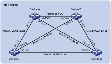
· 网络中所有设备都属于同一个MST域。Device A和Device B为汇聚层设备,Device C和Device D为接入层设备。
· 通过配置MSTP,使不同VLAN的报文按照不同的MSTI转发:VLAN 10的报文沿MSTI 1转发,VLAN 30沿MSTI 3转发,VLAN 40沿MSTI 4转发,VLAN 20沿MSTI 0转发。
· 由于VLAN 10和VLAN 30在汇聚层设备终结、VLAN 40在接入层设备终结,因此配置MSTI 1和MSTI 3的根桥分别为Device A和Device B,MSTI 4的根桥为Device C。
2. 组网图
图1-12 MSTP典型配置组网图

3. 配置步骤
(1) 配置VLAN和端口
请按照图1-12在Device A和Device B上分别创建VLAN 10、20和30,在Device C上创建VLAN 10、20和40,在Device D上创建VLAN 20、30和40;将各设备的各端口配置为Trunk端口并允许相应的VLAN通过,具体配置过程略。
(2) 配置Device A
# 配置MST域的域名为example,将VLAN 10、30、40分别映射到MSTI 1、3、4上,并配置MSTP的修订级别为0。
<DeviceA> system-view
[DeviceA] stp region-configuration
[DeviceA-mst-region] region-name example
[DeviceA-mst-region] instance 1 vlan 10
[DeviceA-mst-region] instance 3 vlan 30
[DeviceA-mst-region] instance 4 vlan 40
[DeviceA-mst-region] revision-level 0
# 激活MST域的配置。
[DeviceA-mst-region] active region-configuration
[DeviceA-mst-region] quit
# 配置本设备为MSTI 1的根桥。
[DeviceA] stp instance 1 root primary
# 全局使能生成树协议。
[DeviceA] stp enable
(3) 配置Device B
# 配置MST域的域名为example,将VLAN 10、30、40分别映射到MSTI 1、3、4上,并配置MSTP的修订级别为0。
<DeviceB> system-view
[DeviceB] stp region-configuration
[DeviceB-mst-region] region-name example
[DeviceB-mst-region] instance 1 vlan 10
[DeviceB-mst-region] instance 3 vlan 30
[DeviceB-mst-region] instance 4 vlan 40
[DeviceB-mst-region] revision-level 0
# 激活MST域的配置。
[DeviceB-mst-region] active region-configuration
[DeviceB-mst-region] quit
# 配置本设备为MSTI 3的根桥。
[DeviceB] stp instance 3 root primary
# 全局使能生成树协议。
[DeviceB] stp enable
(4) 配置Device C
# 配置MST域的域名为example,将VLAN 10、30、40分别映射到MSTI 1、3、4上,并配置MSTP的修订级别为0。
<DeviceC> system-view
[DeviceC] stp region-configuration
[DeviceC-mst-region] region-name example
[DeviceC-mst-region] instance 1 vlan 10
[DeviceC-mst-region] instance 3 vlan 30
[DeviceC-mst-region] instance 4 vlan 40
[DeviceC-mst-region] revision-level 0
# 激活MST域的配置。
[DeviceC-mst-region] active region-configuration
[DeviceC-mst-region] quit
# 配置本设备为MSTI 4的根桥。
[DeviceC] stp instance 4 root primary
# 全局使能生成树协议。
[DeviceC] stp enable
(5) 配置Device D
# 配置MST域的域名为example,将VLAN 10、30、40分别映射到MSTI 1、3、4上,并配置MSTP的修订级别为0。
<DeviceD> system-view
[DeviceD] stp region-configuration
[DeviceD-mst-region] region-name example
[DeviceD-mst-region] instance 1 vlan 10
[DeviceD-mst-region] instance 3 vlan 30
[DeviceD-mst-region] instance 4 vlan 40
[DeviceD-mst-region] revision-level 0
# 激活MST域的配置。
[DeviceD-mst-region] active region-configuration
[DeviceD-mst-region] quit
# 全局使能生成树协议。
[DeviceD] stp enable
(6) 检验配置效果
![]()
在本例中,假定Device B的根桥ID最小,因此该设备将在MSTI 0中被选举为根桥。
当网络拓扑稳定后,通过使用display stp brief命令可以查看各设备上生成树的简要信息。例如:
# 查看Device A上生成树的简要信息。
[DeviceA] display stp brief
MSTID Port Role STP State Protection
0 GigabitEthernet1/0/1 ALTE DISCARDING NONE
0 GigabitEthernet1/0/2 DESI FORWARDING NONE
0 GigabitEthernet1/0/3 ROOT FORWARDING NONE
1 GigabitEthernet1/0/1 DESI FORWARDING NONE
1 GigabitEthernet1/0/3 DESI FORWARDING NONE
3 GigabitEthernet1/0/2 DESI FORWARDING NONE
3 GigabitEthernet1/0/3 ROOT FORWARDING NONE
# 查看Device B上生成树的简要信息。
[DeviceB] display stp brief
MSTID Port Role STP State Protection
0 GigabitEthernet1/0/1 DESI FORWARDING NONE
0 GigabitEthernet1/0/2 DESI FORWARDING NONE
0 GigabitEthernet1/0/3 DESI FORWARDING NONE
1 GigabitEthernet1/0/2 DESI FORWARDING NONE
1 GigabitEthernet1/0/3 ROOT FORWARDING NONE
3 GigabitEthernet1/0/1 DESI FORWARDING NONE
3 GigabitEthernet1/0/3 DESI FORWARDING NONE
# 查看Device C上生成树的简要信息。
[DeviceC] display stp brief
MSTID Port Role STP State Protection
0 GigabitEthernet1/0/1 DESI FORWARDING NONE
0 GigabitEthernet1/0/2 ROOT FORWARDING NONE
0 GigabitEthernet1/0/3 DESI FORWARDING NONE
1 GigabitEthernet1/0/1 ROOT FORWARDING NONE
1 GigabitEthernet1/0/2 ALTE DISCARDING NONE
4 GigabitEthernet1/0/3 DESI FORWARDING NONE
# 查看Device D上生成树的简要信息。
[DeviceD] display stp brief
MSTID Port Role STP State Protection
0 GigabitEthernet1/0/1 ROOT FORWARDING NONE
0 GigabitEthernet1/0/2 ALTE DISCARDING NONE
0 GigabitEthernet1/0/3 ALTE DISCARDING NONE
3 GigabitEthernet1/0/1 ROOT FORWARDING NONE
3 GigabitEthernet1/0/2 ALTE DISCARDING NONE
4 GigabitEthernet1/0/3 ROOT FORWARDING NONE
根据上述显示信息,可以绘出各VLAN所对应MSTI的拓扑,如图1-13所示。
图1-13 各VLAN所对应MSTI的拓扑图

- 2024-02-28回答
- 评论(0)
- 举报
-
(0)


亲~登录后才可以操作哦!
确定你的邮箱还未认证,请认证邮箱或绑定手机后进行当前操作
举报
×
侵犯我的权益
×
侵犯了我企业的权益
×
- 1. 您举报的内容是什么?(请在邮件中列出您举报的内容和链接地址)
- 2. 您是谁?(身份证明材料,可以是身份证或护照等证件)
- 3. 是哪家企业?(营业执照,单位登记证明等证件)
- 4. 您与该企业的关系是?(您是企业法人或被授权人,需提供企业委托授权书)
抄袭了我的内容
×
原文链接或出处
诽谤我
×
- 1. 您举报的内容以及侵犯了您什么权益?(请在邮件中列出您举报的内容、链接地址,并给出简短的说明)
- 2. 您是谁?(身份证明材料,可以是身份证或护照等证件)
对根叔社区有害的内容
×
不规范转载
×
举报说明


暂无评论