★ Comware 7 AP's Association with the AC at Layer 2 Configuration Examples(PSK encryption)
- 0关注
- 0收藏 2278浏览

Network Topology
3.1 Networking requirements
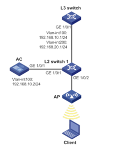
As shown in Figure 3-1, under the centralized forwarding, AC is connected to L2 switch1, AC acts as a DHCP server to assign addresses to APs, and L3 swtich acts as a DHCP server to assigns IP addresses to clients. The wireless client Client needs to be connected to the AC through the AP. The specific requirements are as follows:
• The wireless client Client accesses the network through VLAN 200;
• The AC belongs to VLAN 100, and a connection is established between the AC and the AP through the Layer 2 network.
• L2 switch 1 supplies power to the AP through POE.
Figure 3-1 Network
diagram of a configuration example of a Fit AP registering to the AC through a
Layer 2 network
Configuration Steps
3.4 Procedures
3.4.1 Configuring the L3 switch
1. Configuring the interface of L3 switcth
# Create VLAN 100 and configure an IP address to forward traffic in the CAPWAP tunnel between AC and AP.
<L3 switch> system-view
[L3 switch] vlan 100
[L3 switch-vlan100] quit
[L3 switch] interface vlan-interface 100
[L3 switch-Vlan-interface100] ip address 192.168.10.1 255.255.255.0
[L3 switch-Vlan-interface100] quit
# Create VLAN 200 and configure an IP address for the interface. Client uses this VLAN to access the wireless network。
[L3 switch] vlan 200
[L3 switch-vlan200] quit
[L3 switch] interface vlan-interface 200
[L3 switch-Vlan-interface200] ip address 192.168.20.1 255.255.255.0
[L3 switch-Vlan-interface200] quit
# Configure the interface GigabitEthernet 1/0/1 connecting L3 switch and L2 switch1 to be of trunk type, which prohibits VLAN 1 packets from passing, and allows VLAN 100 and VLAN 200 to pass.
[L3 switch] interface gigabitEthernet 1/0/1
[L3 switch-GigabitEthernet1/0/1] port link-type trunk
[L3 switch-GigabitEthernet1/0/1] undo port trunk permit vlan 1
[L3 switch-GigabitEthernet1/0/1] port trunk permit vlan 100 200
[L3 switch-GigabitEthernet1/0/1] quit
2. Configuring DHCP server
(1) Enable the DHCP server function.
# Enable the DHCP server function.
<L3 switch> system-view
[L3 switch] dhcp enable
(2) # Configure the DHCP address pool client to assign an address range of 192.168.20.0/24 to the client, and the DNS server address assigned to the client is the gateway address (in actual use, please configure the wireless client"s DNS server address according to the actual network plan), and the gateway address is 192.168.20.1.
[L3 switch] dhcp server ip-pool client
[L3 switch-dhcp-pool-2] network 192.168.20.0 mask 255.255.255.0
[L3 switch-dhcp-pool-2] gateway-list 192.168.20.1
[L3 switch-dhcp-pool-2] dns-list 192.168.20.1
[L3 switch-dhcp-pool-2] quit
(1) Configure AC interface
# Create VLAN 100 and its corresponding VLAN interface, and configure an IP address for the interface. The AP will obtain the IP address to establish a CAPWAP tunnel with the AC.
[AC] vlan 100
[AC-vlan100] quit
[AC] interface vlan-interface 100
[AC-Vlan-interface100] ip address 192.168.10.2 255.255.255.0
[AC-Vlan-interface100] quit
# Create VLAN 200, and Client uses this VLAN to access the wireless network.
[AC] vlan 200
[AC-vlan200] quit
# Configure the interface GigabitEthernet 1/0/1 connecting AC and L2 switch 1 to be of trunk type, which prohibits VLAN 1 packets from passing, and allows VLAN 100 and VLAN 200 to pass.
[AC] interface gigabitethernet 1/0/1
[AC-GigabitEthernet1/0/1] port link-type trunk
[AC-GigabitEthernet1/0/1] undo port trunk permit vlan 1
[AC-GigabitEthernet1/0/1] port trunk permit vlan 100 200
[AC-GigabitEthernet1/0/1] quit
(2) Configure wireless services
[AC] wlan service-template 1
[AC-wlan-st-1] ssid service
[AC-wlan-st-1] akm mode psk
[AC-wlan-st-1] preshared-key pass-phrase simple 123456789
[AC-wlan-st-1] cipher-suite ccmp
[AC-wlan-st-1] security-ie rsn
[AC-wlan-st-1] service-template enable
[AC-wlan-st-1] quit
(3) configuring AP
[AC] wlan ap officeap model WA4320i-ACN
[AC-wlan-ap-officeap] serial-id 210235A1Q2C159000018
[AC-wlan-ap-officeap] radio 1
[AC-wlan-ap-officeap-radio-1] service-template 1 vlan 200
[AC-wlan-ap-officeap-radio-1] radio enable
[AC-wlan-ap-officeap-radio-1] quit
(4) Configure a DHCP address pool to automatically assign IP addresses to APs.
<AC> system-view
[AC] dhcp enable
[AC] dhcp server ip-pool ap
[AC-dhcp-pool-1] network 192.168.10.0 mask 255.255.255.0
[AC-dhcp-pool-1] gateway-list 192.168.10.2
[AC-dhcp-pool-1] quit
<L2 switch 1> system-view
[L2 switch 1] vlan 100
[L2 switch 1-vlan100] quit
[L2 switch 1] vlan 200
[L2 switch 1-vlan200] quit
[L2 switch 1] interface gigabitEthernet 1/0/1
[L2 switch 1-GigabitEthernet1/0/1] port link-type trunk
[L2 switch 1-GigabitEthernet1/0/1] undo port trunk permit vlan 1
[L2 switch 1-GigabitEthernet1/0/1] port trunk permit vlan 100 200
[L2 switch 1-GigabitEthernet1/0/1] quit
[L2 switch 1] interfac gigabitEthernet 1/0/2
[L2 switch 1-GigabitEthernet1/0/2] port link-type access
[L2 switch 1-GigabitEthernet1/0/2] port access vlan 100
[L2 switch 1-GigabitEthernet1/0/2] poe enable
[L2 switch 1-GigabitEthernet1/0/2] quit
[L2 switch 1] interface gigabitEthernet 1/0/3
[L2 switch 1-GigabitEthernet1/0/3] port link-type trunk
[L2 switch 1-GigabitEthernet1/0/3] undo port trunk permit vlan 1
[L2 switch 1-GigabitEthernet1/0/3] port trunk permit vlan 100 200
[L2 switch 1-GigabitEthernet1/0/3] quit
3.5 Verifying the configuration
# Verify that the AP is in R/M state.
<AC> display wlan ap all
Total number of APs: 1
Total number of connected APs: 1
Total number of connected manual APs: 1
Total number of connected auto APs: 0
Total number of connected common APs: 1
Total number of connected WTUs: 0
Total number of inside APs: 0
Maximum supported APs: 3072
Remaining APs: 3071
Total AP licenses: 512
Remaining AP licenses: 511
AP information
State : I = Idle, J = Join, JA = JoinAck, IL = ImageLoad
C = Config, DC = DataCheck, R = Run, M = Master, B = Backup
AP name AP ID State Model Serial ID
officeap 1 R/M WA4320i-ACN 210235A1Q2C159000018
Key Configuration
No comments
Add Comments:
✖
案例意见反馈


亲~登录后才可以操作哦!
确定你的邮箱还未认证,请认证邮箱或绑定手机后进行当前操作