CPOS Modules of H3C Series Routers
- 0关注
- 0收藏 745浏览
CPOS Modules of H3C Series Routers
I. Preface
With the development of network broadband, leased-line used in the enterprise and Internet cafe in the past becomes more and more popular. This makes a higher requirement on the port density of access router for increasing users. Channelization technology comes into being in this case. The high density channelization technology is well suited for this high density leased line access approach. Additionally, the bandwidth of access channel can be configured flexibly, meeting users with low access bandwidth and continuous upgrading requirements in the future. All of this aims to two-win goal that operators and users save upgrading costs and thus better adapts to the network change trends. SDH(SONET)becomes the criteria of transport network for its good reliability and flexibility and supports for various services. SDH transport network has gained great development in our country. A variety rate of PDH signals can be mapped and multiplexed to SDH signal. PDH timeslot can be assigned to data channel independently, enabling the access to ultra high density ports by channelizing SDH. SDH channelization technology becomes the key of aggregation router. As the rapidly growing of leased line access requirement, SDH channelization technology will have a better application perspective in our country.
Common PDH signal (E1, T1, E3 and T3) is mapped and multiplexed to SDH signal, and then it accesses the router via interfaces such as high speed STM-1 and STM-4. In this way, an SDH port can enable the access to high density PDH signal. 1×STM-1/OC3 multi-channel interface module of 8040 provides a minimum rate of N×64K. The difference from the previous CPOS module of 8070 is that it reduces the minimum bandwidth of channel to N×64K, not E1/DS1 (including non-channelized and net channel).
When SDH signal is considered by multiplexing low-speed signals, these low-speed tributary signals are referred to as channel. CPOS (i.e. channelized POS interface) takes advantage of the characteristics of SDH system and provides a capability of fine bandwidth partition. As a result, it can reduce the requirement on the number of router low-speed physical ports in networking, enhance the ability of fine bandwidth partition and improve the leased line access capability.
CPOS supports a great number of specifications. According to market requirements, CPOS interface only enables the multiplexing from E1/T1 to STM-1.
In the SDH multiplexing recommended by G.709, there are several multiplexing paths from a payload to STM-N. The multiplexing of E1/T1 to STM-1 is shown as follows respectively:

The multiplexing from E1 to STM-1

The multiplexing from T1 to STM-1
In real environment, the multiplexing path may vary by different countries and regions. In order to guarantee the interworking, CPOS provides multiplex mode command, enabling user to select AU-3 or AU-4 multiplexing path (Optical synchronization transport network technology system in our country uses AU-4 multiplexing path).
Description of Interconnection with CPOS Interface from Other Companies
When it comes to CPOS interface, we employs byte interleave multiplex mode. The lower order containers in a higher order container are not arranged orderly. In order to facilitate user configuration, the following takes that CPOS E1 employs AU-4 multiplex path as an example to introduce the calculation approaches of TU serial number.
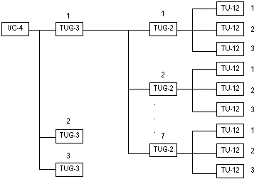
Using AU-4 multiplex path, from the perspective of multiplex process in 0, you will see that the 2Mbit/s multiplex structure is 3-7-3 structure. The formula for calculating the TU-12 numbers at different locations in the same VC-4 is shown as follows:
VC-12 number=TUG-3 number+(TUG-2 number-1)×3+(TU-12 number-1)×21.
In VC-4, TUG-3 number and TUG-2 number are all identical. Two TU-12s that the difference between them is 1 are called as adjacent location.
& Note:
The number in above formula refers to the location number in VC4 frame. The range of TUG-3 number, TUG-2 number and TU-12 number is 1~3, 1~7 and 1~3 respectively. TU-12 serial number means that this TU-12 is which TU-12 of 63 TU-12s in VC-4 frame by multiplex order, i.e. which E1 channel.

The arrangement order of TUG-3, TUG-2 and TU-12 in VC-4
Using AU-3 multiplex path, the serial number calculation approach of TU-12 can be deduced in the same way.
You can directly cite number 1~63 or 1~84 in the case of that the CPOS interface is configured with 63 E1 channels or 84 T1 channels. Using routers from our company in conjunction with channelized STM-1 interface from other company routers, you should pay attention to the number difference caused by different channel citation approaches.
II. Module Introduction
1CPOS is the short of 1-port channelized SDH/SONET interface module, in which C represents Channelized and POS represents Packet Over SDH/Sonet.
1CPOS supports one STM-1/OC3 multi-channel interface module and 155.52Mbit/s channel rate.
1CPOS interface card is broken into two models: 1CPOS (E) and 1CPOS (T), in which 1CPOS (E) interface card supports E1 standard and 1CPOS (T) interface card supports T1 standard.
1CPOS interface module is inserted in MIM or FIC slot in modulized router. It communicates with CPU via PCI interface and completes the receiving/sending of STM-1 channelized POS interface data. Its features are as follows:
AppendixA Supports net channel (non-frame) E1 (up to 63) or T1 (up to 84).
AppendixB Supports non-channelized (frame) E1 (up to 63) or T1 (up to 84).
Supports channelize to 64K with up to 256 logical channels.
III. Module Appearance
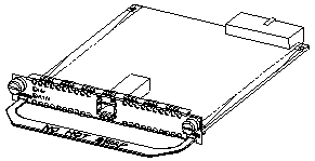
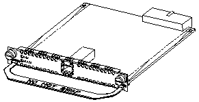
The appearances of 1CPOS (E) and 1CPOS (T) interface modules are identical (only silk-screen is different) with the same interface standards, shown as follows:

1CPOS (E) interface module appearance(MIM card)
The front panel of 1CPOS (E) /1CPOS (T) interface module is shown as follows:

1CPOS interface module front panel (MIM card)

1CPOS interface module front panel (FIC card)
The indicators and its implications of the front panel of 1CPOS (E) and 1CPOS (T) interface modules are identical. The following table shows the implications of various indicators:
1CPOS (E)/1CPOS (T) interface module indicator implication
|
LINK |
Extinguished: represents the link is not connected. Light: represents the link is connected. |
|
ACT |
Flash represents some data has been received/sent. Extinguished represents no data has been received/sent. |
IV. Module Interface Cable
1CPOS module should connect to a fiber with LC-type fiber connector as an interface, so user is required to use a fiber with LC-type fiber connector.

LC type fiber connector appearance
Note:
Fiber connector (also called as live connector): International Telecom Union (ITU) recommends to define it as “an inactive component used to stably but not permanently connect two or more fibers.” As the indispensable inactive component in optical communication system, the use of fiber connector makes it possible to enable a removable connection among optical channels.
There are a great deal of fiber connectors, for example:
(1) FC: cycle fiber connector with screw thread
(2) ST: cycle fiber connector with plug-in
(3) LC: square fiber connector
(4) MT-RJ: square transceiver fiber connector
The optical interface may have invisible radials emitting from it when none of fiber connectors is connected or dustproof cover has been opened, so please do not directly see the optical interface. Closing the dustproof cover is desirable if the optical interface does not install an opticla connector.
V. Module Interface Attribute
The interface attributes of 1CPOS (E)/1CPOS (T) module are shown as follows:
Interface attributes of 1CPOS (E)/1CPOS (T) module
|
Attribute |
Description | ||||
|
Interface standard |
SONET OC-3/SDH STM-1 | ||||
|
Interface number |
1 | ||||
|
Type of connector |
SFP socket (additional SFP optical module is needed, including multimode/single mode/single mode long haul/single mode ultra long haul | ||||
|
Maximum transmission distance |
2km(multimode)/15km (single mode)/40km(single mode long haul)/80km(single mode ultra long haul) | ||||
|
Type of cable |
LC optical | ||||
|
Interface rate |
155.52Mbit/s | ||||
|
Transmitting optical power |
|
Short haul multimode |
Medium haul single mode |
Long haul |
Ultra long haul |
|
Minimum |
-19.0 dBm |
-15.0 dBm |
-5.0 dBm |
-5.0 dBm | |
|
Maximum |
-14.0 dBm |
-8.0 dBm |
0. dBm |
0. dBm | |
|
Receiving sensitivity |
-30.0 dBm |
-28.0 dBm |
-34.0 dBm |
-34.0 dBm | |
|
Overload optical power |
-14.0 dBm |
-7.0 dBm |
-9.0 dBm |
-10.0 dBm | |
|
Core wavelength |
1310nm |
1310nm |
1310nm |
1550nm | |
|
Supported link protocol |
PPP Frame relay HDLC | ||||
Note:
The transmission distance of long haul optical interface can not too close, or you can not receive signals. The transmission distance is required larger than 25km. In this case, you can use optical attenuator to reduce input optical power.
VI. Module Networking Description
CPOS interface configuration includes:
l Enter the designated CPOS interface view
l Set CPOS frame format
Whether CPOS port is applied under SONET mode or SDH mode is depending on frame format.
l Set CPOS clock mode
CPOS interface supports two clock modes:
Master clock mode: use internal clock signal
Slave clock mode: use clock signal provided by line
When it is attached to SONET/SDH device, due to the clock precision of SONET/SDH network is higher than the internal clock precision of CPOS itself, the CPOS should be configured with slave clock mode. If two CPOS ports are directly connected each other via fiber, one end should be configured with master clock mode, the other should be slave clock mode.
l Set CPOS loopback mode
l Set CPOS AUG multiplexing path
In SDH, there are two kinds of mapping/multiplexing approaches for load:
In ANSI multiplexing, the lower order load is aggregated in VC-3 higher order channel. VC-3 plus an AU pointer becomes management unit AU-3. Then three of this AU-3 multiplexes simultaneously to a management unit group AUG.
In ETSI multiplexing, the lower order load is aggregated in VC-4 higher-order channel. VC-4 plus an AU pointer becomes management unit AU-4. Then one of this AU-4 multiplexes simultaneously to a management unit group AUG.
l Set section overhead byte and higher-order channel byte
At the Controller-level of CPOS, you can configure regenerator section trace byte J0, channel trace byte J1 and signal label byte C2.
J0 is subject to section overhead byte, used to check the continuity of connection between two ports at section-level. J1 and C2 are subject to higher-order channel overhead byte. The former is used to check the continuity of connection between two ports at channel-level, and the later is used to indicate the multiplexing structure of VC frame and the characteristics of information payload.
Regenerator trace byte j0 can use 1~15 long string. By default, hexadecimal value 01 is sent circularly for compatible with previous devices.
Channel trace byte j1 can use 1~15 long string. By default, NetEngine string is sent circularly.
C2 is primarily used for interworking worldwide and 0x02 is used in home. By default, c2 value is 02 (hexadecimal).
l Set the frame format of E1/T1 channel
E1 channel supports a frame format with 4bit CRC (Cyclic Redundancy Check).
T1 channel supports SF (Super Frame) and ESF (Extended Super Frame) frame formats.
l Set the clock mode of E1/T1 channel
l Set the loopback mode of E1/T1 channel
l Set the operational mode of E1/T1 channel
In real environment, CPOS channelized E1 supports two operational modes: net channel (also called as unframed) and unchannelized.
Under net channel mode, E1 does not differentiate timeslots, forming a 2.048Mbit/s serial port called as serial slot/card/port/c1-number: 0.
Under unchannelized mode, other 31 timeslots (except for timeslot 0) of E1 channel are bound as a serial port.
CPOS channelized T1 supports two operational modes: net channel (also called as unframed) and channelized.
Under net channel mode, T1 does not differentiate timeslots, forming a 1.544Mbit/s serial port called as serial slot/card/t1-number: 0.
Under channelized mode, all 24 timeslots of T1 channel can be bound freely as a serial port.
l Set the timeslot bind of E1/T1 channel
l Enter bound port view
该案例暂时没有网友评论
编辑评论
✖
案例意见反馈


亲~登录后才可以操作哦!
确定你的邮箱还未认证,请认证邮箱或绑定手机后进行当前操作