S5120
- 0关注
- 1收藏,1827浏览

问题描述:
默认情况下,S5120交换机链路聚合是什么模式,怎么配置手工和静态lacp
- 2021-01-26提问
- 举报
-
(0)
最佳答案


缺省情况下,二层报文根据源/目的MAC地址进行聚合负载分担,三层报文根据源/目的MAC地址及源/目的IP地址进行聚合负载分担
以太网链路聚合典型配置举例
在聚合组中,只有端口属性类配置(请参见“1.1 5. 配置分类”)和第二类配置(请参见“1.1 5. 配置分类”)都与参考端口(请参见“1.1 6. 参考端口”)相同的成员端口才可以成为选中端口。因此,用户需通过配置使各成员端口的上述配置与参考端口保持一致,而除此以外的其它配置则只需在聚合接口上进行,不必再在成员端口上重复配置。
1.8.1 静态聚合配置举例
1. 组网需求
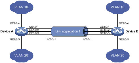
· Device A与Device B通过各自的以太网端口GigabitEthernet1/0/1~GigabitEthernet1/0/3相互连接。
· 在Device A和Device B上分别配置静态链路聚合组,并使两端的VLAN 10和VLAN 20之间分别互通。
· 通过按照报文的源MAC地址和目的MAC地址进行聚合负载分担的方式,来实现数据流量在各成员端口间的负载分担。
2. 组网图
图1-5 静态聚合配置组网图
3. 配置步骤
(1) 配置Device A
# 创建VLAN 10,并将端口GigabitEthernet1/0/4加入到该VLAN中。
<DeviceA> system-view
[DeviceA] vlan 10
[DeviceA-vlan10] port gigabitethernet 1/0/4
[DeviceA-vlan10] quit
# 创建VLAN 20,并将端口GigabitEthernet1/0/5加入到该VLAN中。
[DeviceA] vlan 20
[DeviceA-vlan20] port gigabitethernet 1/0/5
[DeviceA-vlan20] quit
# 创建二层聚合接口1。
[DeviceA] interface bridge-aggregation 1
[DeviceA-Bridge-Aggregation1] quit
# 分别将端口GigabitEthernet1/0/1至 GigabitEthernet1/0/3加入到聚合组1中。
[DeviceA] interface gigabitethernet 1/0/1
[DeviceA-gigabitethernet1/0/1] port link-aggregation group 1
[DeviceA-gigabitethernet1/0/1] quit
[DeviceA] interface gigabitethernet 1/0/2
[DeviceA-gigabitethernet1/0/2] port link-aggregation group 1
[DeviceA-gigabitethernet1/0/2] quit
[DeviceA] interface gigabitethernet 1/0/3
[DeviceA-gigabitethernet1/0/3] port link-aggregation group 1
[DeviceA-gigabitethernet1/0/3] quit
# 配置二层聚合接口1为Trunk端口,并允许VLAN 10和20的报文通过。
![]()
该配置将被自动同步到聚合组1内的所有成员端口上。
[DeviceA] interface bridge-aggregation 1
[DeviceA-Bridge-Aggregation1] port link-type trunk
[DeviceA-Bridge-Aggregation1] port trunk permit vlan 10 20
Please wait... Done.
Configuring GigabitEthernet1/0/1... Done.
Configuring GigabitEthernet1/0/2... Done.
Configuring GigabitEthernet1/0/3... Done.
[DeviceA-Bridge-Aggregation1] quit
# 配置全局按照报文的源MAC地址和目的MAC地址进行聚合负载分担。
[DeviceA] link-aggregation load-sharing mode source-mac destination-mac
(2) 配置Device B
Device B的配置与Device A相似,配置过程略。
(3) 检验配置效果
# 查看Device A上所有聚合组的摘要信息。
[DeviceA] display link-aggregation summary
Aggregation Interface Type:
BAGG -- Bridge-Aggregation, RAGG -- Route-Aggregation
Aggregation Mode: S -- Static, D -- Dynamic
Loadsharing Type: Shar -- Loadsharing, NonS -- Non-Loadsharing
Actor System ID: 0x8000, 000f-e2ff-0001
AGG AGG Partner ID Select Unselect Share
Interface Mode Ports Ports Type
-------------------------------------------------------------------------------
BAGG1 S none 3 0 Shar
以上信息表明,聚合组1为负载分担类型的静态聚合组,包含有三个选中端口。
# 查看Device A上全局采用的聚合负载分担类型。
[DeviceA] display link-aggregation load-sharing mode
Link-Aggregation Load-Sharing Mode:
destination-mac address, source-mac address
以上信息表明,所有聚合组都按照报文的源MAC地址和目的MAC地址进行聚合负载分担。
1.8.2 动态聚合配置举例
1. 组网需求
· Device A与Device B通过各自的以太网端口GigabitEthernet1/0/1~GigabitEthernet1/0/3相互连接。
· 在Device A和Device B上分别配置动态链路聚合组,并使两端的VLAN 10和VLAN 20之间分别互通。
· 通过按照报文的源MAC地址和目的MAC地址进行聚合负载分担的方式,来实现数据流量在各成员端口间的负载分担。
2. 组网图
图1-6 动态聚合配置组网图
3. 配置步骤
(1) 配置Device A
# 创建VLAN 10,并将端口GigabitEthernet1/0/4加入到该VLAN中。
<DeviceA> system-view
[DeviceA] vlan 10
[DeviceA-vlan10] port gigabitethernet 1/0/4
[DeviceA-vlan10] quit
# 创建VLAN 20,并将端口GigabitEthernet1/0/5加入到该VLAN中。
[DeviceA] vlan 20
[DeviceA-vlan20] port gigabitethernet 1/0/5
[DeviceA-vlan20] quit
# 创建二层聚合接口1,并配置该接口为动态聚合模式。
[DeviceA] interface bridge-aggregation 1
[DeviceA-Bridge-Aggregation1] link-aggregation mode dynamic
[DeviceA-Bridge-Aggregation1] quit
# 分别将端口GigabitEthernet1/0/1至 GigabitEthernet1/0/3加入到聚合组1中。
[DeviceA] interface gigabitethernet 1/0/1
[DeviceA-gigabitethernet1/0/1] port link-aggregation group 1
[DeviceA-gigabitethernet1/0/1] quit
[DeviceA] interface gigabitethernet 1/0/2
[DeviceA-gigabitethernet1/0/2] port link-aggregation group 1
[DeviceA-gigabitethernet1/0/2] quit
[DeviceA] interface gigabitethernet 1/0/3
[DeviceA-gigabitethernet1/0/3] port link-aggregation group 1
[DeviceA-gigabitethernet1/0/3] quit
# 配置二层聚合接口1为Trunk端口,并允许VLAN 10和20的报文通过。
![]()
该配置将被自动同步到聚合组1内的所有成员端口上。
[DeviceA] interface bridge-aggregation 1
[DeviceA-Bridge-Aggregation1] port link-type trunk
[DeviceA-Bridge-Aggregation1] port trunk permit vlan 10 20
Please wait... Done.
Configuring GigabitEthernet1/0/1... Done.
Configuring GigabitEthernet1/0/2... Done.
Configuring GigabitEthernet1/0/3... Done.
[DeviceA-Bridge-Aggregation1] quit
# 配置全局按照报文的源MAC地址和目的MAC地址进行聚合负载分担。
[DeviceA] link-aggregation load-sharing mode source-mac destination-mac
(2) 配置Device B
Device B的配置与Device A相似,配置过程略。
(3) 检验配置效果
# 查看Device A上所有聚合组的摘要信息。
[DeviceA] display link-aggregation summary
Aggregation Interface Type:
BAGG -- Bridge-Aggregation, RAGG -- Route-Aggregation
Aggregation Mode: S -- Static, D -- Dynamic
Loadsharing Type: Shar -- Loadsharing, NonS -- Non-Loadsharing
Actor System ID: 0x8000, 000f-e2ff-0001
AGG AGG Partner ID Select Unselect Share
Interface Mode Ports Ports Type
-------------------------------------------------------------------------------
BAGG1 D 0x8000, 000f-e2ff-0002 3 0 Shar
以上信息表明,聚合组1为负载分担类型的二层动态聚合组,包含有三个选中端口。
# 查看Device A上全局采用的聚合负载分担类型。
[DeviceA] display link-aggregation load-sharing mode
Link-Aggregation Load-Sharing Mode:
destination-mac address, source-mac address
以上信息表明,所有聚合组都按照报文的源MAC地址和目的MAC地址进行聚合负载分担。
- 2021-01-26回答
- 评论(0)
- 举报
-
(0)
暂无评论


默认的链路聚合是 静态聚合,配置如下:
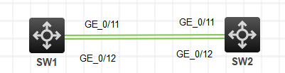
SW1
int Bridge-Aggregation 1
quit
int g1/0/11
port link-aggregation group 1
quit
int g1/0/12
port link-aggregation group 1
quit
int Bridge-Aggregation 1
port link-type trunk
port trunk permit vlan all
sa f
SW2
int Bridge-Aggregation 1
quit
int g1/0/11
port link-aggregation group 1
quit
int g1/0/12
port link-aggregation group 1
quit
int Bridge-Aggregation 1
port link-type trunk
port trunk permit vlan all
sa f
- 2021-01-26回答
- 评论(0)
- 举报
-
(0)
暂无评论

您好,请知:
默认是在静态的模式下。
以下是链路聚合的配置命令,请参考:
[SW1]int Bridge-Aggregation 1 //创建链路聚合组1
[SW1-Bridge-Aggregation1]quit
[SW1]int range gi 1/0/1 to gi 1/0/2
[SW1-if-range]port link-aggregation group 1 //将链路聚合组应用到接口
[SW1-if-range]quit
[SW1]int Bridge-Aggregation 1 //继续配置链路聚合组1
[SW1-Bridge-Aggregation1]port link-type trunk
Configuring GigabitEthernet1/0/1 done.
Configuring GigabitEthernet1/0/2 done.
[SW1-Bridge-Aggregation1]undo port trunk permit vlan 1
Configuring GigabitEthernet1/0/1 done.
Configuring GigabitEthernet1/0/2 done.
[SW1-Bridge-Aggregation1]port trunk permit vlan 10
Configuring GigabitEthernet1/0/1 done.
Configuring GigabitEthernet1/0/2 done.
[SW1-Bridge-Aggregation1]quit
参考举例如下:
以太网链路聚合典型配置举例
在聚合组中,只有端口属性类配置(请参见“1.1 5. 配置分类”)和第二类配置(请参见“1.1 5. 配置分类”)都与参考端口(请参见“1.1 6. 参考端口”)相同的成员端口才可以成为选中端口。因此,用户需通过配置使各成员端口的上述配置与参考端口保持一致,而除此以外的其它配置则只需在聚合接口上进行,不必再在成员端口上重复配置。
1.8.1 静态聚合配置举例
1. 组网需求
· Device A与Device B通过各自的以太网端口GigabitEthernet1/0/1~GigabitEthernet1/0/3相互连接。
· 在Device A和Device B上分别配置静态链路聚合组,并使两端的VLAN 10和VLAN 20之间分别互通。
· 通过按照报文的源MAC地址和目的MAC地址进行聚合负载分担的方式,来实现数据流量在各成员端口间的负载分担。
2. 组网图
图1-5 静态聚合配置组网图
3. 配置步骤
(1) 配置Device A
# 创建VLAN 10,并将端口GigabitEthernet1/0/4加入到该VLAN中。
<DeviceA> system-view
[DeviceA] vlan 10
[DeviceA-vlan10] port gigabitethernet 1/0/4
[DeviceA-vlan10] quit
# 创建VLAN 20,并将端口GigabitEthernet1/0/5加入到该VLAN中。
[DeviceA] vlan 20
[DeviceA-vlan20] port gigabitethernet 1/0/5
[DeviceA-vlan20] quit
# 创建二层聚合接口1。
[DeviceA] interface bridge-aggregation 1
[DeviceA-Bridge-Aggregation1] quit
# 分别将端口GigabitEthernet1/0/1至 GigabitEthernet1/0/3加入到聚合组1中。
[DeviceA] interface gigabitethernet 1/0/1
[DeviceA-gigabitethernet1/0/1] port link-aggregation group 1
[DeviceA-gigabitethernet1/0/1] quit
[DeviceA] interface gigabitethernet 1/0/2
[DeviceA-gigabitethernet1/0/2] port link-aggregation group 1
[DeviceA-gigabitethernet1/0/2] quit
[DeviceA] interface gigabitethernet 1/0/3
[DeviceA-gigabitethernet1/0/3] port link-aggregation group 1
[DeviceA-gigabitethernet1/0/3] quit
# 配置二层聚合接口1为Trunk端口,并允许VLAN 10和20的报文通过。
![]()
该配置将被自动同步到聚合组1内的所有成员端口上。
[DeviceA] interface bridge-aggregation 1
[DeviceA-Bridge-Aggregation1] port link-type trunk
[DeviceA-Bridge-Aggregation1] port trunk permit vlan 10 20
Please wait... Done.
Configuring GigabitEthernet1/0/1... Done.
Configuring GigabitEthernet1/0/2... Done.
Configuring GigabitEthernet1/0/3... Done.
[DeviceA-Bridge-Aggregation1] quit
# 配置全局按照报文的源MAC地址和目的MAC地址进行聚合负载分担。
[DeviceA] link-aggregation load-sharing mode source-mac destination-mac
(2) 配置Device B
Device B的配置与Device A相似,配置过程略。
(3) 检验配置效果
# 查看Device A上所有聚合组的摘要信息。
[DeviceA] display link-aggregation summary
Aggregation Interface Type:
BAGG -- Bridge-Aggregation, RAGG -- Route-Aggregation
Aggregation Mode: S -- Static, D -- Dynamic
Loadsharing Type: Shar -- Loadsharing, NonS -- Non-Loadsharing
Actor System ID: 0x8000, 000f-e2ff-0001
AGG AGG Partner ID Select Unselect Share
Interface Mode Ports Ports Type
-------------------------------------------------------------------------------
BAGG1 S none 3 0 Shar
以上信息表明,聚合组1为负载分担类型的静态聚合组,包含有三个选中端口。
# 查看Device A上全局采用的聚合负载分担类型。
[DeviceA] display link-aggregation load-sharing mode
Link-Aggregation Load-Sharing Mode:
destination-mac address, source-mac address
以上信息表明,所有聚合组都按照报文的源MAC地址和目的MAC地址进行聚合负载分担。
1.8.2 动态聚合配置举例
1. 组网需求
· Device A与Device B通过各自的以太网端口GigabitEthernet1/0/1~GigabitEthernet1/0/3相互连接。
· 在Device A和Device B上分别配置动态链路聚合组,并使两端的VLAN 10和VLAN 20之间分别互通。
· 通过按照报文的源MAC地址和目的MAC地址进行聚合负载分担的方式,来实现数据流量在各成员端口间的负载分担。
2. 组网图
图1-6 动态聚合配置组网图
3. 配置步骤
(1) 配置Device A
# 创建VLAN 10,并将端口GigabitEthernet1/0/4加入到该VLAN中。
<DeviceA> system-view
[DeviceA] vlan 10
[DeviceA-vlan10] port gigabitethernet 1/0/4
[DeviceA-vlan10] quit
# 创建VLAN 20,并将端口GigabitEthernet1/0/5加入到该VLAN中。
[DeviceA] vlan 20
[DeviceA-vlan20] port gigabitethernet 1/0/5
[DeviceA-vlan20] quit
# 创建二层聚合接口1,并配置该接口为动态聚合模式。
[DeviceA] interface bridge-aggregation 1
[DeviceA-Bridge-Aggregation1] link-aggregation mode dynamic
[DeviceA-Bridge-Aggregation1] quit
# 分别将端口GigabitEthernet1/0/1至 GigabitEthernet1/0/3加入到聚合组1中。
[DeviceA] interface gigabitethernet 1/0/1
[DeviceA-gigabitethernet1/0/1] port link-aggregation group 1
[DeviceA-gigabitethernet1/0/1] quit
[DeviceA] interface gigabitethernet 1/0/2
[DeviceA-gigabitethernet1/0/2] port link-aggregation group 1
[DeviceA-gigabitethernet1/0/2] quit
[DeviceA] interface gigabitethernet 1/0/3
[DeviceA-gigabitethernet1/0/3] port link-aggregation group 1
[DeviceA-gigabitethernet1/0/3] quit
# 配置二层聚合接口1为Trunk端口,并允许VLAN 10和20的报文通过。
![]()
该配置将被自动同步到聚合组1内的所有成员端口上。
[DeviceA] interface bridge-aggregation 1
[DeviceA-Bridge-Aggregation1] port link-type trunk
[DeviceA-Bridge-Aggregation1] port trunk permit vlan 10 20
Please wait... Done.
Configuring GigabitEthernet1/0/1... Done.
Configuring GigabitEthernet1/0/2... Done.
Configuring GigabitEthernet1/0/3... Done.
[DeviceA-Bridge-Aggregation1] quit
# 配置全局按照报文的源MAC地址和目的MAC地址进行聚合负载分担。
[DeviceA] link-aggregation load-sharing mode source-mac destination-mac
(2) 配置Device B
Device B的配置与Device A相似,配置过程略。
(3) 检验配置效果
# 查看Device A上所有聚合组的摘要信息。
[DeviceA] display link-aggregation summary
Aggregation Interface Type:
BAGG -- Bridge-Aggregation, RAGG -- Route-Aggregation
Aggregation Mode: S -- Static, D -- Dynamic
Loadsharing Type: Shar -- Loadsharing, NonS -- Non-Loadsharing
Actor System ID: 0x8000, 000f-e2ff-0001
AGG AGG Partner ID Select Unselect Share
Interface Mode Ports Ports Type
-------------------------------------------------------------------------------
BAGG1 D 0x8000, 000f-e2ff-0002 3 0 Shar
以上信息表明,聚合组1为负载分担类型的二层动态聚合组,包含有三个选中端口。
# 查看Device A上全局采用的聚合负载分担类型。
[DeviceA] display link-aggregation load-sharing mode
Link-Aggregation Load-Sharing Mode:
destination-mac address, source-mac address
以上信息表明,所有聚合组都按照报文的源MAC地址和目的MAC地址进行聚合负载分担。
- 2021-01-26回答
- 评论(0)
- 举报
-
(0)
暂无评论
编辑答案


亲~登录后才可以操作哦!
确定你的邮箱还未认证,请认证邮箱或绑定手机后进行当前操作
举报
×
侵犯我的权益
×
侵犯了我企业的权益
×
- 1. 您举报的内容是什么?(请在邮件中列出您举报的内容和链接地址)
- 2. 您是谁?(身份证明材料,可以是身份证或护照等证件)
- 3. 是哪家企业?(营业执照,单位登记证明等证件)
- 4. 您与该企业的关系是?(您是企业法人或被授权人,需提供企业委托授权书)
抄袭了我的内容
×
原文链接或出处
诽谤我
×
- 1. 您举报的内容以及侵犯了您什么权益?(请在邮件中列出您举报的内容、链接地址,并给出简短的说明)
- 2. 您是谁?(身份证明材料,可以是身份证或护照等证件)
对根叔社区有害的内容
×
不规范转载
×
举报说明
暂无评论