两台华三7503交换机配置成VRRP,主路由器优先级都是200,备用路由器保持默认优先级是100就可以,能否在备用交换机上把部分优先级也设置成200,对网络有没有影响
- 0关注
- 1收藏,3785浏览

问题描述:
两台华三7503交换机配置成VRRP,主路由器优先级都是200,备用路由器保持默认优先级是100就可以,能否在备用交换机上把部分优先级也设置成200,对网络有没有影响
组网及组网描述:
- 2021-06-17提问
- 举报
-
(0)


可以的,多配几个vrrp组就行了,没影响,但是要结合MSTP一起使用,不同MSTP组,根桥在不同的交换机上
- 2021-06-17回答
- 评论(2)
- 举报
-
(0)
VRRP与MSTP组网的,两个核心交换机直接必须要有心跳线吗?
1.1 VRRP简介
VRRP用来为网关设备提供冗余备份。如图1-1所示,VRRP将可以承担网关功能的一组设备加入到备份组中,形成一台虚拟路由器,局域网内的主机将此虚拟路由器设置为缺省网关。VRRP根据优先级从备份组中选举出一台网关设备作为Master,负责转发局域网内主机与外部通信的流量,其他网关设备作为Backup。当Master出现故障后,VRRP重新选举新的Master,保证流量转发不会中断。
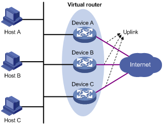
VRRP可以监视上行接口或链路的状态。当路由器的上行接口或链路出现故障时,该路由器主动降低自己的优先级,使得备份组内其它路由器的优先级高于这个路由器,以避免这个路由器成为Master,导致流量转发失败。
1.2 MSTP简介
MSTP是在STP的基础上发展而来的,用于在局域网中消除数据链路层的物理环路。作为一种二层管理协议,MSTP通过选择性地阻塞网络中的冗余链路来消除二层环路,将环路网络结构修剪成无环路的树型网络结构,从而防止报文在环路网络中不断增生和无限循环,避免设备由于重复接收相同报文而造成报文处理能力的下降;同时,它还具备链路备份的功能。与STP相比,MSTP可以实现网络拓扑的快速收敛,也能使不同VLAN的流量沿各自的路径转发,从而为冗余链路提供了更好的负载分担机制。
2 应用场合
2.1 单独使用VRRP的组网方式
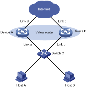
单独使用VRRP为网关提供冗余备份的组网方式如图1-2所示:局域网内的主机通过二层交换机接入两台网关设备Device A和Device B,Device A和Device B构成一台虚拟路由器,为网关提供冗余备份,以提高网关设备的可靠性。这种组网方式虽然可以防止网关的单点故障,但是仍然存在以下问题:
· 不能防御所有的链路故障。例如,链路a和链路c同时发生故障时,局域网内的主机将无法与外界通信。
· 链路a或链路b出现故障时,即使Master正常工作,也会导致Backup接收不到Master发送的VRRP通告报文,从而错误地认为Master出现故障,进行Master和Backup状态切换。
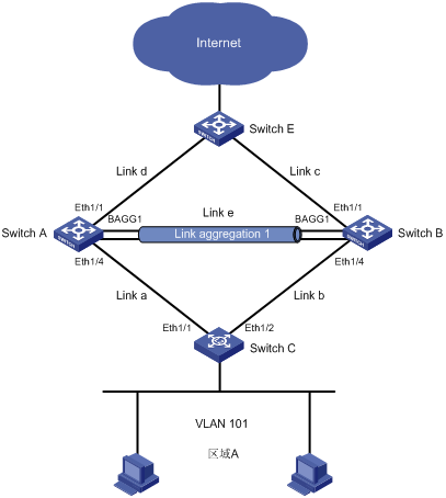
2.2 VRRP与MSTP配合使用的组网方式
图1-3 VRRP与MSTP配合使用提高网络可靠性
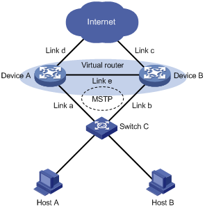
VRRP与MSTP配合使用的组网方式如图1-3所示:在Device A和Device B之间增加心跳线(链路e)为下行链路提供冗余备份,并使用MSTP技术阻塞网络中的冗余链路以消除二层环路。采用这种组网方式,不仅可以为网关设备提供冗余备份,还可以为下行的二层链路提供冗余备份,极大地提高了网络的可靠性。VRRP与MSTP配合使用的组网方式具有以下优势:
· 可以防御多种链路故障。只要上行链路(链路c和链路d)、下行链路(链路a和链路b)中各有一条可达链路,即可保证通信不会中断。例如,Device A作为Master时,如果链路a和链路c同时出现故障,则通过链路b—链路e—链路d这条路径转发流量;如果链路a和链路d同时出现故障,则通过VRRP监视上行接口或链路功能降低Device A的优先级,使得Device B成为Master,流量通过链路b—链路c这条路径转发;如果链路a和链路e同时出现故障,则Device B接收不到Device A的通告报文,使得Device B成为Master,流量通过链路b—链路c这条路径转发。
· 通过在Device A和Device B之间增加心跳线,避免链路a或链路b出现故障、网关正常工作时错误地进行Master和Backup状态切换。
![]()
在VRRP与MSTP配合使用的组网方式中,心跳线链路e通常为聚合链路,以提高可靠性。
3 配置前提
本文档不严格与具体软、硬件版本对应,如果使用过程中与产品实际情况有差异,请参考相关产品手册,或以设备实际情况为准。
本文档中的配置均是在实验室环境下进行的配置和验证,配置前设备的所有参数均采用出厂时的缺省配置。如果您已经对设备进行了配置,为了保证配置效果,请确认现有配置和以下举例中的配置不冲突。
4 配置举例
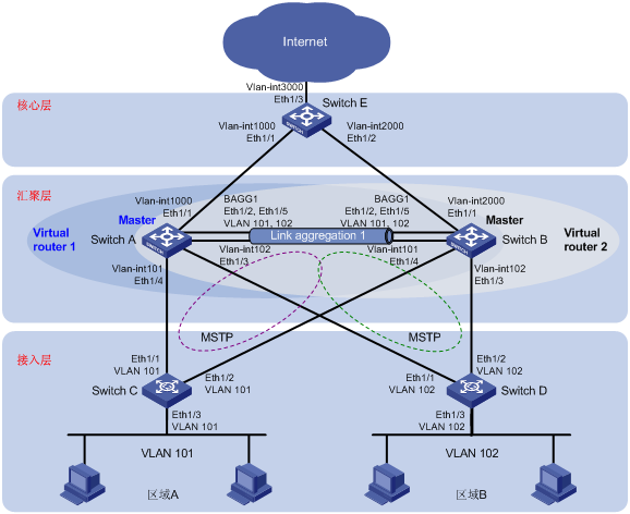
4.1 组网需求
· 局域网中采用VRRP技术进行网关设备的备份,提高网关的可靠性。当一台网关设备出现故障时,局域网内的主机仍然可以通过另一台网关设备访问外部网络。
· 在网关设备工作正常时,区域A用户通过网关设备Switch A进行数据转发;区域B用户通过网关设备Switch B进行数据转发,实现流量的负载分担。
· 当网关设备的上行链路出现故障时,降低该网关设备的优先级,以避免该网关设备成为Master,导致流量转发中断。
· 局域网内进行二层链路的冗余备份,保证网关设备下行链路故障时,流量转发不会中断。使用MSTP技术避免二层网络中出现环路。
· 网关设备通过核心层的出口设备Switch E与Internet连接。
![]()
通常情况下,核心层会部署多台出口设备,以提高网络的可靠性。为了简化配置过程,本文仅以一台出口设备为例,说明出口设备的配置方法。多台出口设备时,配置方法与此类似。
图1-4 VRRP与MSTP综合配置组网图
接口 | IP地址 | 设备 | 接口 | IP地址 | |
Switch A | Vlan-int101 | 10.1.1.2/24 | Switch B | Vlan-int101 | 10.1.1.3/24 |
| Vlan-int102 | 10.2.1.2/24 |
| Vlan-int102 | 10.2.1.3/24 |
| Vlan-int1000 | 100.0.0.2/24 |
| Vlan-int2000 | 200.0.0.2/24 |
| Virtual IP 1 | 10.1.1.1/24 |
| Virtual IP 1 | 10.1.1.1/24 |
| Virtual IP 2 | 10.2.1.1/24 |
| Virtual IP 2 | 10.2.1.1/24 |
Switch E | Vlan-int1000 | 100.0.0.1/24 |
|
|
|
| Vlan-int2000 | 200.0.0.1/24 |
|
|
|
| Vlan-int3000 | 30.0.0.1/24 |
|
|
|
4.2 配置思路
实现上述组网需求,需要进行如下配置:
· Switch A、Switch B上分别创建两个VRRP备份组。
· 配置Switch A在备份组1内具有更高的优先级,即正常情况下Switch A作为备份组1的Master设备;配置Switch B在备份组2内具有更高的优先级,即正常情况下Switch B作为备份组2的Master设备。
· 区域A内的主机将备份组1的虚拟IP地址设置为网关,区域B内的主机将备份组2的虚拟IP地址设置为网关。从而保证在网关设备工作正常时,区域A用户通过网关设备Switch A进行数据转发,区域B用户通过网关设备Switch B进行数据转发,实现流量的负载分担。
· Switch A、Switch B上分别配置VRRP备份组监视上行接口,当上行接口出现故障时,降低路由器在备份组中的优先级。
· Switch A、Switch B和二层交换机之间启用MSTP多实例,并在各实例中指定根桥和备份根桥。
· 在Switch A、Switch B和Switch E之间配置OSPF路由协议。Switch A和Switch B通过OSPF发布区域A和区域B所在网段的路由,以实现区域A与区域B内主机与外部网络的三层互通。并在Switch A和Switch B上合理配置路由的Cost值,以便内网访问外网、外网访问内网的双向流量通过同一台设备处理。
· Switch A和Switch B之间的链路采用聚合链路,以提高心跳线的可靠性。
4.3 配置步骤
4.3.1 设备A的配置
# 配置端口Ethernet1/1属于VLAN 1000、Ethernet1/3属于VLAN 102、Ethernet1/4属于VLAN 101。
<SwitchA> system-view
[SwitchA] vlan 1000
[SwitchA-vlan1000] port ethernet 1/1
[SwitchA-vlan1000] quit
[SwitchA] vlan 101
[SwitchA-vlan101] port ethernet 1/4
[SwitchA-vlan101] quit
[SwitchA] vlan 102
[SwitchA-vlan102] port ethernet 1/3
[SwitchA-vlan102] quit
# 创建二层聚合接口1。
[SwitchA] interface bridge-aggregation 1
[SwitchA-Bridge-Aggregation1] quit
# 分别将端口Ethernet1/2和Ethernet1/5加入到聚合组1中。
[SwitchA] interface ethernet 1/2
[SwitchA-Ethernet1/2] port link-aggregation group 1
[SwitchA-Ethernet1/2] quit
[SwitchA] interface ethernet 1/5
[SwitchA-Ethernet1/5] port link-aggregation group 1
[SwitchA-Ethernet1/5] quit
# 配置二层聚合接口1为Trunk端口,并允许VLAN 101和102的报文通过。
[SwitchA] interface bridge-aggregation 1
[SwitchA-Bridge-Aggregation1] port link-type trunk
[SwitchA-Bridge-Aggregation1] port trunk permit vlan 101 to 102
[SwitchA-Bridge-Aggregation1] undo port trunk permit vlan 1
[SwitchA-Bridge-Aggregation1] port trunk pvid vlan 101
[SwitchA-Bridge-Aggregation1] quit
# 配置上行接口IP地址。
[SwitchA] interface vlan-interface 1000
[SwitchA-Vlan-interface1000] ip address 100.0.0.2 24
[SwitchA-Vlan-interface1000] quit
# 创建Track项1,监视上行接口的物理状态。
[SwitchA] track 1 interface vlan-interface 1000
# 创建VRRP备份组1,配置Switch A在备份组1中的优先级为110。
[SwitchA] interface vlan-interface 101
[SwitchA-Vlan-interface101] ip address 10.1.1.2 24
[SwitchA-Vlan-interface101] vrrp vrid 1 virtual-ip 10.1.1.1
[SwitchA-Vlan-interface101] vrrp vrid 1 priority 110
# 配置VRRP备份组1监视Track项1的状态。当Track项状态为Negative(即上行接口的物理状态为down)时,Switch A在备份组1的优先级降低20,使得Switch B的优先级高于Switch A,Switch B成为Master。
[SwitchA-Vlan-interface101] vrrp vrid 1 track 1 reduced 20
[SwitchA-Vlan-interface101] quit
# 创建VRRP备份组2。
[SwitchA] interface vlan-interface 102
[SwitchA-Vlan-interface102] ip address 10.2.1.2 24
[SwitchA-Vlan-interface102] vrrp vrid 1 virtual-ip 10.2.1.1
[SwitchA–Vlan-interface102] quit
# 配置MSTP。
[SwitchA] stp region-configuration
[SwitchA-mst-region] region-name vrrp
[SwitchA-mst-region] instance 1 vlan 101
[SwitchA-mst-region] instance 2 vlan 102
[SwitchA-mst-region] active region-configuration
[SwitchA-mst-region] quit
[SwitchA] stp instance 1 root primary
[SwitchA] stp instance 2 root secondary
[SwitchA] stp enable
# 在上行接口上关闭STP功能。
[SwitchA] interface ethernet 1/1
[SwitchA-Ethernet1/1] undo stp enable
[SwitchA-Ethernet1/1] quit
# 配置OSPF发布网段路由。
[SwitchA] ospf
[SwitchA-ospf-1] area 0
[SwitchA-ospf-1-area-0.0.0.0] network 100.0.0.0 0.0.0.255
[SwitchA-ospf-1-area-0.0.0.0] network 10.1.1.0 0.0.0.255
[SwitchA-ospf-1-area-0.0.0.0] network 10.2.1.0 0.0.0.255
[SwitchA-ospf-1-area-0.0.0.0] quit
[SwitchA-ospf-1] quit
# 配置接口Vlan-int102的路由Cost值为5,以便外网访问区域B的报文优先通过Switch B转发。
[SwitchA] interface vlan-interface 102
[SwitchA-Vlan-interface102] ospf cost 5
[SwitchA-Vlan-interface102] quit
4.3.2 设备B的配置
# 配置端口Ethernet1/1属于VLAN 2000、Ethernet1/3属于VLAN 102、Ethernet1/4属于VLAN 101。
<SwitchB> system-view
[SwitchB] vlan 2000
[SwitchB-vlan2000] port ethernet 1/1
[SwitchB-vlan2000] quit
[SwitchB] vlan 101
[SwitchB-vlan101] port ethernet 1/4
[SwitchB-vlan101] quit
[SwitchB] vlan 102
[SwitchB-vlan102] port ethernet 1/3
[SwitchB-vlan102] quit
# 创建二层聚合接口1。
[SwitchB] interface bridge-aggregation 1
[SwitchB-Bridge-Aggregation1] quit
# 分别将端口Ethernet1/2和Ethernet1/5加入到聚合组1中。
[SwitchB] interface ethernet 1/2
[SwitchB-Ethernet1/2] port link-aggregation group 1
[SwitchB-Ethernet1/2] quit
[SwitchB] interface ethernet 1/5
[SwitchB-Ethernet1/5] port link-aggregation group 1
[SwitchB-Ethernet1/5] quit
# 配置二层聚合接口1为Trunk端口,并允许VLAN 101和102的报文通过。
[SwitchB] interface bridge-aggregation 1
[SwitchB-Bridge-Aggregation1] port link-type trunk
[SwitchB-Bridge-Aggregation1] port trunk permit vlan 101 to 102
[SwitchB-Bridge-Aggregation1] undo port trunk permit vlan 1
[SwitchB-Bridge-Aggregation1] port trunk pvid vlan 101
[SwitchB-Bridge-Aggregation1] quit
# 配置上行接口IP地址。
[SwitchB] interface vlan-interface 2000
[SwitchB-Vlan-interface2000] ip address 200.0.0.2 24
[SwitchB-Vlan-interface2000] quit
# 创建Track项1,监视上行接口的物理状态。
[SwitchB] track 1 interface vlan-interface 2000
# 创建VRRP备份组1。
[SwitchB] interface vlan-interface 101
[SwitchB-Vlan-interface101] ip address 10.1.1.3 24
[SwitchB-Vlan-interface101] vrrp vrid 1 virtual-ip 10.1.1.1
[SwitchB–Vlan-interface101] quit
# 创建VRRP备份组2,配置Switch B在备份组2中的优先级为110。
[SwitchB] interface vlan-interface 102
[SwitchB-Vlan-interface102] ip address 10.2.1.3 24
[SwitchB-Vlan-interface102] vrrp vrid 1 virtual-ip 10.2.1.1
[SwitchB-Vlan-interface102] vrrp vrid 1 priority 110
# 配置VRRP备份组2监视Track项1的状态。当Track项状态为Negative(即上行接口的物理状态为down)时,Switch B在备份组2的优先级降低20,使得Switch A的优先级高于Switch B,Switch A成为Master。
[SwitchB-Vlan-interface102] vrrp vrid 1 track 1 reduced 20
[SwitchB-Vlan-interface102] quit
# 配置MSTP。
[SwitchB] stp region-configuration
[SwitchB-mst-region] region-name vrrp
[SwitchB-mst-region] instance 1 vlan 101
[SwitchB-mst-region] instance 2 vlan 102
[SwitchB-mst-region] active region-configuration
[SwitchB-mst-region] quit
[SwitchB] stp instance 2 root primary
[SwitchB] stp instance 1 root secondary
[SwitchB] stp enable
# 在上行接口上关闭STP功能。
[SwitchB] interface ethernet 1/1
[SwitchB-Ethernet1/1] undo stp enable
[SwitchB-Ethernet1/1] quit
# 配置OSPF发布网段路由。
[SwitchB] ospf
[SwitchB-ospf-1] area 0
[SwitchB-ospf-1-area-0.0.0.0] network 200.0.0.0 0.0.0.255
[SwitchB-ospf-1-area-0.0.0.0] network 10.1.1.0 0.0.0.255
[SwitchB-ospf-1-area-0.0.0.0] network 10.2.1.0 0.0.0.255
[SwitchB-ospf-1-area-0.0.0.0] quit
[SwitchB-ospf-1] quit
# 配置接口Vlan-int101的路由Cost值为5,以便外网访问区域A的报文优先通过Switch A转发。
[SwitchB] interface vlan-interface 101
[SwitchB-Vlan-interface102] ospf cost 5
[SwitchB-Vlan-interface102] quit
4.3.3 设备C的配置
# 配置VLAN 101。
<SwitchC> system-view
[SwitchC] vlan 101
[SwitchC-vlan101] port ethernet 1/1 to ethernet 1/3
[SwitchC-vlan101] quit
# 配置MSTP。
[SwitchC] stp region-configuration
[SwitchC-mst-region] region-name vrrp
[SwitchC-mst-region] instance 1 vlan 101
[SwitchC-mst-region] instance 2 vlan 102
[SwitchC-mst-region] active region-configuration
[SwitchC-mst-region] quit
[SwitchC] stp enable
4.3.4 设备D的配置
# 配置VLAN 102。
<SwitchD> system-view
[SwitchD] vlan 102
[SwitchD-vlan102] port ethernet 1/1 to ethernet 1/3
[SwitchD-vlan102] quit
# 配置MSTP。
[SwitchD] stp region-configuration
[SwitchD-mst-region] region-name vrrp
[SwitchD-mst-region] instance 1 vlan 101
[SwitchD-mst-region] instance 2 vlan 102
[SwitchD-mst-region] active region-configuration
[SwitchD-mst-region] quit
[SwitchD] stp enable
4.3.5 设备E的配置
# 配置VLAN 1000。
<SwitchE> system-view
[SwitchE] vlan 1000
[SwitchE-vlan1000] port ethernet 1/1
[SwitchE-vlan1000] quit
# 配置接口Vlan-int1000的IP地址。
[SwitchE] interface vlan-interface 1000
[SwitchE-Vlan-interface1000] ip address 100.0.0.1 24
[SwitchE-Vlan-interface1000] quit
# 配置VLAN 2000。
[SwitchE] vlan 2000
[SwitchE-vlan2000] port ethernet 1/2
[SwitchE-vlan2000] quit
# 配置接口Vlan-int2000的IP地址。
[SwitchE] interface vlan-interface 2000
[SwitchE-Vlan-interface2000] ip address 200.0.0.1 24
[SwitchE-Vlan-interface2000] quit
# 配置VLAN 3000。
[SwitchE] vlan 3000
[SwitchE-vlan3000] port ethernet 1/3
[SwitchE-vlan3000] quit
# 配置接口Vlan-int3000的IP地址。
[SwitchE] interface vlan-interface 3000
[SwitchE-Vlan-interface3000] ip address 30.0.0.1 24
[SwitchE-Vlan-interface3000] quit
# 配置OSPF发布网段路由。
[SwitchE] ospf
[SwitchE-ospf-1] area 0
[SwitchE-ospf-1-area-0.0.0.0] network 100.0.0.0 0.0.0.255
[SwitchE-ospf-1-area-0.0.0.0] network 200.0.0.0 0.0.0.255
[SwitchE-ospf-1-area-0.0.0.0] network 30.0.0.0 0.0.0.255
[SwitchE-ospf-1-area-0.0.0.0] quit
[SwitchE-ospf-1] quit
4.3.6 主机的配置
配置区域A内主机的缺省网关为10.1.1.1,区域B内主机的缺省网关为10.2.1.1,具体配置过程略。
4.4 验证配置
(1) 网关设备和链路均正常工作时,验证局域网内主机是否可以与外部网络通信
# 在Switch A和Switch B上查看VRRP备份组的信息。可以看到Switch A在备份组1中为Master,Switch B在备份组2中为Master,从而保证区域A的主机通过Switch A与外部通信,区域B的主机通过Switch B与外部通信。
<SwitchA> display vrrp
IPv4 Standby Information:
Run Mode : Standard
Run Method : Virtual MAC
Total number of virtual routers : 2
Interface VRID State Run Adver Auth Virtual
Pri Timer Type IP
---------------------------------------------------------------------
Vlan101 1 Master 110 1 None 10.1.1.1
Vlan102 1 Backup 100 1 None 10.2.1.1
<SwitchB> display vrrp
IPv4 Standby Information:
Run Mode : Standard
Run Method : Virtual MAC
Total number of virtual routers : 2
Interface VRID State Run Adver Auth Virtual
Pri Timer Type IP
---------------------------------------------------------------------
Vlan101 1 Backup 100 1 None 10.1.1.1
Vlan102 1 Master 110 1 None 10.2.1.1
# 在Switch C上查看生成树状态。可以看到端口Ethernet1/2为替换端口,不可以转发流量,从而避免环路。
<SwitchC> display stp brief
MSTID Port Role STP State Protection
1 Ethernet1/1 ROOT FORWARDING NONE
1 Ethernet1/2 ALTE DISCARDING NONE
1 Ethernet1/3 DESI FORWARDING NONE
# 在Switch D上查看生成树状态。可以看到端口Ethernet1/1为替换端口,不可以转发流量,从而避免环路。
<SwitchD> display stp brief
MSTID Port Role STP State Protection
2 Ethernet1/1 ALTE DISCARDING NONE
2 Ethernet1/2 ROOT FORWARDING NONE
2 Ethernet1/3 DESI FORWARDING NONE
# 在区域A和区域B的主机上ping 30.0.0.1,可以ping通。
C:\> ping 30.0.0.1
Pinging 30.0.0.1 with 32 bytes of data:
Reply from 30.0.0.1: bytes=32 time=19ms TTL=254
Reply from 30.0.0.1: bytes=32 time<1ms TTL=254
Reply from 30.0.0.1: bytes=32 time<1ms TTL=254
Reply from 30.0.0.1: bytes=32 time<1ms TTL=254
Ping statistics for 30.0.0.1:
Packets: Sent = 4, Received = 4, Lost = 0 (0% loss),
Approximate round trip times in milli-seconds:
Minimum = 0ms, Maximum = 19ms, Average = 4ms
# 在Switch A、Switch B和Switch E上开启ICMP超时报文发送功能。
<SwitchA> system-view
[SwitchA] ip ttl-expires enable
<SwitchB> system-view
[SwitchB] ip ttl-expires enable
<SwitchE> system-view
[SwitchE] ip ttl-expires enable
# 在区域A内IP地址为10.1.1.4的主机上查看到达30.0.0.1的报文所经过的路径。可以看出,区域A内访问外网的报文通过Switch A转发。
C:\> tracert 30.0.0.1
Tracing route to 30.0.0.1 over a maximum of 30 hops
1 23 ms 1 ms 1 ms 10.1.1.2
2 <1 ms <1 ms <1 ms 30.0.0.1
Trace complete.
# 在区域B内IP地址为10.2.1.4的主机上查看到达30.0.0.1的报文所经过的路径。可以看出,区域B内访问外网的报文通过Switch B转发。
C:\> tracert 30.0.0.1
Tracing route to 30.0.0.1 over a maximum of 30 hops
1 13 ms 1 ms 1 ms 10.2.1.3
2 <1 ms <1 ms <1 ms 30.0.0.1
Trace complete.
# 在Switch E上查看到达10.1.1.4(区域A内某主机的IP地址)的报文所经过的路径。可以看出,外网访问区域A内主机的报文通过Switch A转发。
[SwitchE] tracert 10.1.1.4
traceroute to 10.1.1.4(10.1.1.4) 30 hops max,40 bytes packet, press CTRL_C to break
1 100.0.0.2 2 ms 1 ms 1 ms
2 10.1.1.4 <1 ms 1 ms 1 ms
# 在Switch E上查看到达10.2.1.4(区域B内某主机的IP地址)的报文所经过的路径。可以看出,外网访问区域B内主机的报文通过Switch B转发。
[SwitchE] tracert 10.2.1.4
traceroute to 10.2.1.4(10.2.1.4) 30 hops max,40 bytes packet, press CTRL_C to break
1 200.0.0.2 1 ms 2 ms 1 ms
2 10.2.1.4 1 ms 1 ms 1 ms
(2) 一台网关设备出现故障后,验证局域网内主机是否可以与外部网络通信
# 保存当前配置后,重启Switch A。
<SwitchA> save config.cfg
The current configuration will be saved to flash:/config.cfg. Continue? [Y/N]:y
flash:/config.cfg exists, overwrite? [Y/N]:y
Now saving current configuration to the device.
Saving configuration flash:/config.cfg. Please wait...
.........................
Configuration is saved to flash successfully.
<SwitchA> reboot
Start to check configuration with next startup configuration file, please wait.
........DONE!
This command will reboot the device. Continue? [Y/N]:y
# 在Switch B上查看VRRP备份组的信息。可以看到Switch B在备份组1和备份组2中均为Master,区域A和区域B的流量均通过Switch B转发。
<SwitchB> display vrrp
IPv4 Standby Information:
Run Mode : Standard
Run Method : Virtual MAC
Total number of virtual routers : 2
Interface VRID State Run Adver Auth Virtual
Pri Timer Type IP
---------------------------------------------------------------------
Vlan101 1 Master 100 1 None 10.1.1.1
Vlan102 1 Master 110 1 None 10.2.1.1
# 在区域A和区域B的主机上ping 30.0.0.1,均可以ping通。(具体验证过程略)
# 在区域A内IP地址为10.1.1.4的主机上查看到达30.0.0.1的报文所经过的路径。可以看出,区域A内访问外网的报文通过Switch B转发。
C:\> tracert 30.0.0.1
Tracing route to 30.0.0.1 over a maximum of 30 hops
1 12 ms 1 ms 1 ms 10.1.1.3
2 <1 ms <1 ms <1 ms 30.0.0.1
Trace complete.
# 在区域B内IP地址为10.2.1.4的主机上查看到达30.0.0.1的报文所经过的路径。可以看出,区域B内访问外网的报文通过Switch B转发。
C:\> tracert 30.0.0.1
Tracing route to 30.0.0.1 over a maximum of 30 hops
1 23 ms 1 ms 1 ms 10.2.1.3
2 <1 ms <1 ms <1 ms 30.0.0.1
Trace complete.
# 在Switch E上查看到达10.1.1.4(区域A内某主机的IP地址)的报文所经过的路径。可以看出,外网访问区域A内主机的报文通过Switch B转发。
<SwitchE> tracert 10.1.1.4
traceroute to 10.1.1.4(10.1.1.4) 30 hops max,40 bytes packet, press CTRL_C to break
1 200.0.0.2 1 ms 1 ms 1 ms
2 10.1.1.4 1 ms 1 ms 1 ms
# 在Switch E上查看到达10.2.1.4(区域B内某主机的IP地址)的报文所经过的路径。可以看出,外网访问区域B内主机的报文通过Switch B转发。
<SwitchE> tracert 10.2.1.4
traceroute to 10.2.1.4(10.2.1.4) 30 hops max,40 bytes packet, press CTRL_C to break
1 200.0.0.2 1 ms 2 ms 1 ms
2 10.2.1.4 1 ms 1 ms 1 ms
(3) 链路出现故障时,验证局域网内主机是否可以与外部网络通信
区域A和区域B的网络是对称的,此处仅以区域A为例,验证链路出现故障时,局域网内主机是否可以与外部网络通信。为了简化描述,对区域A与外部网络通信过程中涉及的链路进行命名,如图1-5所示。
图1-5 区域A与外部通信的网络
· 链路a和链路c同时出现故障时,验证局域网内主机是否可以与外部网络通信
# 在Switch A上关闭接口Ethernet1/4。
<SwitchA> system-view
[SwitchA] interface ethernet 1/4
[SwitchA-Ethernet1/4] shutdown
[SwitchA-Ethernet1/4] quit
# 在Switch B上关闭接口Ethernet1/1。
<SwitchB> system-view
[SwitchB] interface ethernet 1/1
[SwitchB-Ethernet1/1] shutdown
[SwitchB-Ethernet1/1] quit
# 在Switch A和Switch B上查看VRRP备份组的信息。可以看到由于上行接口故障,Switch B在备份组2中的优先级降低为90。Switch A在备份组1和备份组2中均为Master,区域A和区域B的流量均通过Switch A转发。
[SwitchA] display vrrp
IPv4 Standby Information:
Run Mode : Standard
Run Method : Virtual MAC
Total number of virtual routers : 2
Interface VRID State Run Adver Auth Virtual
Pri Timer Type IP
---------------------------------------------------------------------
Vlan101 1 Master 110 1 None 10.1.1.1
Vlan102 1 Master 100 1 None 10.2.1.1
[SwitchB] display vrrp
IPv4 Standby Information:
Run Mode : Standard
Run Method : Virtual MAC
Total number of virtual routers : 2
Interface VRID State Run Adver Auth Virtual
Pri Timer Type IP
---------------------------------------------------------------------
Vlan101 1 Backup 100 1 None 10.1.1.1
Vlan102 1 Backup 90 1 None 10.2.1.1
# 在Switch C上查看生成树状态。可以看到端口Ethernet1/2变为根端口,可以转发流量。
<SwitchC> display stp brief
MSTID Port Role STP State Protection
1 Ethernet1/2 ROOT FORWARDING NONE
1 Ethernet1/3 DESI FORWARDING NONE
# 在区域A的主机上ping 30.0.0.1,可以ping通。(具体验证过程略)
# 在区域A内IP地址为10.1.1.4的主机上查看到达30.0.0.1的报文所经过的路径。可以看出,区域A内访问外网的报文通过Switch A转发。
C:\> tracert 30.0.0.1
Tracing route to 30.0.0.1 over a maximum of 30 hops
1 12 ms 1 ms 1 ms 10.1.1.2
2 <1 ms <1 ms <1 ms 30.0.0.1
Trace complete.
# 在Switch E上查看到达10.1.1.4(区域A内某主机的IP地址)的报文所经过的路径。可以看出,外网访问区域A内主机的报文通过Switch A转发。
<SwitchE> tracert 10.1.1.4
traceroute to 10.1.1.4(10.1.1.4) 30 hops max,40 bytes packet, press CTRL_C to break
1 100.0.0.2 2 ms 2 ms 1 ms
2 10.1.1.4 1 ms 1 ms 1 ms
· 链路a和链路d同时出现故障时,验证局域网内主机是否可以与外部网络通信
# 在Switch A上关闭接口Ethernet1/1和Ethernet1/4。
<SwitchA> system-view
[SwitchA] interface ethernet 1/1
[SwitchA-Ethernet1/1] shutdown
[SwitchA-Ethernet1/1] quit
[SwitchA] interface ethernet 1/4
[SwitchA-Ethernet1/4] shutdown
[SwitchA-Ethernet1/4] quit
# 在Switch A和Switch B上查看VRRP备份组的信息。可以看到由于上行接口故障,Switch A在备份组1中的优先级降低为90。Switch B在备份组1和备份组2中均为Master,区域A和区域B的流量均通过Switch B转发。
[SwitchA] display vrrp
IPv4 Standby Information:
Run Mode : Standard
Run Method : Virtual MAC
Total number of virtual routers : 2
Interface VRID State Run Adver Auth Virtual
Pri Timer Type IP
---------------------------------------------------------------------
Vlan101 1 Backup 90 1 None 10.1.1.1
Vlan102 1 Backup 100 1 None 10.2.1.1
[SwitchB] display vrrp
IPv4 Standby Information:
Run Mode : Standard
Run Method : Virtual MAC
Total number of virtual routers : 2
Interface VRID State Run Adver Auth Virtual
Pri Timer Type IP
---------------------------------------------------------------------
Vlan101 1 Master 100 1 None 10.1.1.1
Vlan102 1 Master 110 1 None 10.2.1.1
# 在Switch C上查看生成树状态。可以看到端口Ethernet1/2为根端口,可以转发流量。
<SwitchC> display stp brief
MSTID Port Role STP State Protection
1 Ethernet1/2 ROOT FORWARDING NONE
1 Ethernet1/3 DESI FORWARDING NONE
# 在区域A的主机上ping 30.0.0.1,可以ping通。(具体验证过程略)
# 在区域A内IP地址为10.1.1.4的主机上查看到达30.0.0.1的报文所经过的路径。可以看出,区域A内访问外网的报文通过Switch B转发。
C:\> tracert 30.0.0.1
Tracing route to 30.0.0.1 over a maximum of 30 hops
1 12 ms 1 ms 1 ms 10.1.1.3
2 1 ms <1 ms <1 ms 30.0.0.1
Trace complete.
# 在Switch E上查看到达10.1.1.4(区域A内某主机的IP地址)的报文所经过的路径。可以看出,外网访问区域A内主机的报文通过Switch B转发。
<SwitchE> tracert 10.1.1.4
traceroute to 10.1.1.4(10.1.1.4) 30 hops max,40 bytes packet, press CTRL_C to break
1 200.0.0.2 2 ms 1 ms 1 ms
2 10.1.1.4 <1 ms 1 ms 2 ms
· 链路a和链路e同时出现故障时,验证局域网内主机是否可以与外部网络通信
# 在Switch A上关闭接口Ethernet1/4和二层聚合接口1。
<SwitchA> system-view
[SwitchA] interface ethernet 1/4
[SwitchA-Ethernet1/4] shutdown
[SwitchA-Ethernet1/4] quit
[SwitchA] interface bridge-aggregation 1
[SwitchA-Bridge-Aggregation1] shutdown
[SwitchA-Bridge-Aggregation1] quit
# 在Switch B上查看VRRP备份组的信息。可以看到Switch B在备份组1和备份组2中均为Master,区域A和区域B的流量均通过Switch B转发。
[SwitchB] display vrrp
IPv4 Standby Information:
Run Mode : Standard
Run Method : Virtual MAC
Total number of virtual routers : 2
Interface VRID State Run Adver Auth Virtual
Pri Timer Type IP
---------------------------------------------------------------------
Vlan101 1 Master 100 1 None 10.1.1.1
Vlan102 1 Master 110 1 None 10.2.1.1
# 在区域A的主机上ping 30.0.0.1,可以ping通。(具体验证过程略)
# 在区域A内IP地址为10.1.1.4的主机上查看到达30.0.0.1的报文所经过的路径。可以看出,区域A内访问外网的报文通过Switch B转发。
C:\> tracert 30.0.0.1
Tracing route to 30.0.0.1 over a maximum of 30 hops
1 12 ms 1 ms 1 ms 10.1.1.3
2 <1 ms <1 ms <1 ms 30.0.0.1
Trace complete.
# 在Switch E上查看到达10.1.1.4(区域A内某主机的IP地址)的报文所经过的路径。可以看出,外网访问区域A内主机的报文通过Switch B转发。
<SwitchE> tracert 10.1.1.4
traceroute to 10.1.1.4(10.1.1.4) 30 hops max,40 bytes packet, press CTRL_C to break
1 200.0.0.2 2 ms 2 ms 2 ms
2 10.1.1.4 1 ms 1 ms <1 ms
· 链路d和链路e同时出现故障时,验证局域网内主机是否可以与外部网络通信
# 在Switch A上关闭接口Ethernet1/1和二层聚合接口1。
<SwitchA> system-view
[SwitchA] interface ethernet 1/1
[SwitchA-Ethernet1/1] shutdown
[SwitchA-Ethernet1/1] quit
[SwitchA] interface bridge-aggregation 1
[SwitchA-Bridge-Aggregation1] shutdown
[SwitchA-Bridge-Aggregation1] quit
# 在Switch A和Switch B上查看VRRP备份组的信息。可以看到由于上行接口故障,Switch A在备份组1中的优先级降低为90。Switch B在备份组1和备份组2中均为Master,区域A和区域B的流量均通过Switch B转发。
[SwitchA] display vrrp
IPv4 Standby Information:
Run Mode : Standard
Run Method : Virtual MAC
Total number of virtual routers : 2
Interface VRID State Run Adver Auth Virtual
Pri Timer Type IP
---------------------------------------------------------------------
Vlan101 1 Backup 90 1 None 10.1.1.1
Vlan102 1 Backup 100 1 None 10.2.1.1
[SwitchB] display vrrp
IPv4 Standby Information:
Run Mode : Standard
Run Method : Virtual MAC
Total number of virtual routers : 2
Interface VRID State Run Adver Auth Virtual
Pri Timer Type IP
---------------------------------------------------------------------
Vlan101 1 Master 100 1 None 10.1.1.1
Vlan102 1 Master 110 1 None 10.2.1.1
# 在Switch C上查看生成树状态。可以看到端口Ethernet1/2为指定端口,可以转发流量。
<SwitchC> display stp brief
MSTID Port Role STP State Protection
1 Ethernet1/1 ROOT FORWARDING NONE
1 Ethernet1/2 DESI FORWARDING NONE
1 Ethernet1/3 DESI FORWARDING NONE
# 在区域A的主机上ping 30.0.0.1,可以ping通。(具体验证过程略)
# 在区域A内IP地址为10.1.1.4的主机上查看到达30.0.0.1的报文所经过的路径。可以看出,区域A内访问外网的报文通过Switch B转发。
C:\> tracert 30.0.0.1
Tracing route to 30.0.0.1 over a maximum of 30 hops
1 12 ms 1 ms 8 ms 10.1.1.3
2 1 ms <1 ms <1 ms 30.0.0.1
Trace complete.
# 在Switch E上查看到达10.1.1.4(区域A内某主机的IP地址)的报文所经过的路径。可以看出,外网访问区域A内主机的报文通过Switch B转发。
<SwitchE> tracert 10.1.1.4
traceroute to 10.1.1.4(10.1.1.4) 30 hops max,40 bytes packet, press CTRL_C to break
1 200.0.0.2 2 ms 2 ms 2 ms
2 10.1.1.4 1 ms 1 ms <1 ms
4.5 配置文件
· 设备A:
#
vlan 101 to 102
#
vlan 1000
#
stp region-configuration
region-name vrrp
instance 1 vlan 101
instance 2 vlan 102
active region-configuration
#
stp instance 1 root primary
stp instance 2 root secondary
stp enable
#
interface Bridge-Aggregation1
port link-type trunk
undo port trunk permit vlan 1
port trunk permit vlan 101 to 102
port trunk pvid vlan 101
#
interface Vlan-interface101
ip address 10.1.1.2 255.255.255.0
vrrp vrid 1 virtual-ip 10.1.1.1
vrrp vrid 1 priority 110
vrrp vrid 1 track 1 reduced 20
#
interface Vlan-interface102
ip address 10.2.1.2 255.255.255.0
ospf cost 5
vrrp vrid 1 virtual-ip 10.2.1.1
#
interface Vlan-interface1000
ip address 100.0.0.2 255.255.255.0
#
interface Ethernet1/1
port link-mode bridge
port access vlan 1000
stp disable
#
interface Ethernet1/2
port link-mode bridge
port link-type trunk
undo port trunk permit vlan 1
port trunk permit vlan 101 to 102
port trunk pvid vlan 101
port link-aggregation group 1
#
interface Ethernet1/3
port link-mode bridge
port access vlan 102
#
interface Ethernet1/4
port link-mode bridge
port access vlan 101
#
interface Ethernet1/5
port link-mode bridge
port link-type trunk
undo port trunk permit vlan 1
port trunk permit vlan 101 to 102
port trunk pvid vlan 101
port link-aggregation group 1
#
ospf 1
area 0.0.0.0
network 100.0.0.0 0.0.0.255
network 10.1.1.0 0.0.0.255
network 10.2.1.0 0.0.0.255
#
track 1 interface Vlan-interface1000
#
· 设备B :
#
vlan 101 to 102
#
vlan 2000
#
stp region-configuration
region-name vrrp
instance 1 vlan 101
instance 2 vlan 102
active region-configuration
#
stp instance 1 root secondary
stp instance 2 root primary
stp enable
#
interface Bridge-Aggregation1
port link-type trunk
undo port trunk permit vlan 1
port trunk permit vlan 101 to 102
port trunk pvid vlan 101
#
interface Vlan-interface101
ip address 10.1.1.3 255.255.255.0
ospf cost 5
vrrp vrid 1 virtual-ip 10.1.1.1
#
interface Vlan-interface102
ip address 10.2.1.3 255.255.255.0
vrrp vrid 1 virtual-ip 10.2.1.1
vrrp vrid 1 priority 110
vrrp vrid 1 track 1 reduced 20
#
interface Vlan-interface2000
ip address 200.0.0.2 255.255.255.0
#
interface Ethernet1/1
port link-mode bridge
port access vlan 2000
stp disable
#
interface Ethernet1/2
port link-mode bridge
port link-type trunk
undo port trunk permit vlan 1
port trunk permit vlan 101 to 102
port trunk pvid vlan 101
port link-aggregation group 1
#
interface Ethernet1/3
port link-mode bridge
port access vlan 102
#
interface Ethernet1/4
port link-mode bridge
port access vlan 101
#
interface Ethernet1/5
port link-mode bridge
port link-type trunk
undo port trunk permit vlan 1
port trunk permit vlan 101 to 102
port trunk pvid vlan 101
port link-aggregation group 1
#
ospf 1
area 0.0.0.0
network 10.1.1.0 0.0.0.255
network 10.2.1.0 0.0.0.255
network 200.0.0.0 0.0.0.255
#
track 1 interface Vlan-interface2000
#
· 设备C:
#
vlan 101
#
stp region-configuration
region-name vrrp
instance 1 vlan 101
instance 2 vlan 102
active region-configuration
#
stp enable
#
interface Ethernet1/1
port link-mode bridge
port access vlan 101
#
interface Ethernet1/2
port link-mode bridge
port access vlan 101
#
interface Ethernet1/3
port link-mode bridge
port access vlan 101
#
· 设备D:
#
vlan 102
#
stp region-configuration
region-name vrrp
instance 1 vlan 101
instance 2 vlan 102
active region-configuration
#
stp enable
#
interface Ethernet1/1
port link-mode bridge
port access vlan 102
#
interface Ethernet1/2
port link-mode bridge
port access vlan 102
#
interface Ethernet1/3
port link-mode bridge
port access vlan 102
#
· 设备E:
#
vlan 1000
#
vlan 2000
#
vlan 3000
#
interface Vlan-interface1000
ip address 100.0.0.1 255.255.255.0
#
interface Vlan-interface2000
ip address 200.0.0.1 255.255.255.0
#
interface Vlan-interface3000
ip address 30.0.0.1 255.255.255.0
#
interface Ethernet1/1
port link-mode bridge
port access vlan 1000
#
interface Ethernet1/2
port link-mode bridge
port access vlan 2000
#
interface Ethernet1/3
port link-mode bridge
port access vlan 3000
#
ospf 1
area 0.0.0.0
network 100.0.0.0 0.0.0.255
network 200.0.0.0 0.0.0.255
network 30.0.0.0 0.0.0.255
- 2021-06-17回答
- 评论(1)
- 举报
-
(0)
stp instance 0 root secondary 是什么意思,包括哪些vlan
stp instance 0 root secondary 是什么意思,包括哪些vlan
编辑答案


亲~登录后才可以操作哦!
确定你的邮箱还未认证,请认证邮箱或绑定手机后进行当前操作
举报
×
侵犯我的权益
×
侵犯了我企业的权益
×
- 1. 您举报的内容是什么?(请在邮件中列出您举报的内容和链接地址)
- 2. 您是谁?(身份证明材料,可以是身份证或护照等证件)
- 3. 是哪家企业?(营业执照,单位登记证明等证件)
- 4. 您与该企业的关系是?(您是企业法人或被授权人,需提供企业委托授权书)
抄袭了我的内容
×
原文链接或出处
诽谤我
×
- 1. 您举报的内容以及侵犯了您什么权益?(请在邮件中列出您举报的内容、链接地址,并给出简短的说明)
- 2. 您是谁?(身份证明材料,可以是身份证或护照等证件)
对根叔社区有害的内容
×
不规范转载
×
举报说明
不需要单独的心跳线啊,都是业务线互联就行