问题描述:
msr 8300 建立 l2tp vpn 服务器的建立 总公司在A地 分公司在B地 总公司使用的是 MSR 8300路由器 怎么把 A与B 建立VPN隧道 B的可以访问到 A的内网 怎么使用 WEB 设置
组网及组网描述:
- 2021-07-21提问
- 举报
-
(0)
最佳答案

您好,请知:
以下是L2TP VPN独立LAC的配置案例,请参考:
https://zhiliao.h3c.com/theme/details/101880

组网说明:
本案例是采用H3C HCL模拟器来模拟L2TP组网中的独立LAC模式。内网和外网已在网络拓扑图中有了明确的标识。内网1和内网2属于两个不同的内网,LAC和LNS分别代表两个内网的出口,不仅承担内网终端访问外网的出口NAT转换,还要作为L2TP隧道建立的两个端点,其中内网1的出口设备作为LAC,内网2的出口设备作为LNS。在完成L2TP组往前,内网1和内网2不能互通,在完成L2TP组网后,内网1和内网2的终端能够互通。其中内网1的LAC不仅作为L2TP的LAC端,还要作为本内网的PPPOE服务器,为终端提供宽带的接入。
配置步骤
1、按照网络拓扑图正确配置IP地址
2、LAC和LNS分别配置NAT,并指向默认路由到外网
3、LAC配置为PPPOE,为内网1的终端提供PPPOE的宽带接入
4、在完成L2TP配置前,内网1和内网2不能互通
5、完成L2TP隧道的建立后,内网1能PING通内网2的终端
配置关键点
第一阶段调试(基础网络配置):
LAC:
<H3C>sys
System View: return to User View with Ctrl+Z.
[H3C]sysname LAC
[LAC]local-user weijianing class network
New local user added.
[LAC-luser-network-weijianing]password simple weijianing
[LAC-luser-network-weijianing]service-type ppp
[LAC-luser-network-weijianing]quit
[LAC]domain name system
[LAC-isp-system]authentication ppp local
[LAC-isp-system]quit
[LAC]ip pool weijianing 192.168.10.2 192.168.10.254
[LAC]int Virtual-Template 1
[LAC-Virtual-Template1]ip address 192.168.10.1 255.255.255.0
[LAC-Virtual-Template1]ppp authentication-mode pap domain system
[LAC-Virtual-Template1]remote address pool weijianing
[LAC-Virtual-Template1]quit
[LAC]int gi 0/0
[LAC-GigabitEthernet0/0]pppoe-server bind virtual-template 1
[LAC-GigabitEthernet0/0]quit
[LAC]acl basic 2000
[LAC-acl-ipv4-basic-2000]rule 0 permit source any
[LAC-acl-ipv4-basic-2000]quit
[LAC]int gi 0/1
[LAC-GigabitEthernet0/1]des <connect to ISP>
[LAC-GigabitEthernet0/1]ip address 202.1.100.2 30
[LAC-GigabitEthernet0/1]nat outbound 2000
[LAC-GigabitEthernet0/1]quit
[LAC]ip route-static 0.0.0.0 0.0.0.0 202.1.100.1
ISP:
<H3C>sys
System View: return to User View with Ctrl+Z.
[H3C]sysname ISP
[ISP]int gi 0/0
[ISP-GigabitEthernet0/0]des <connect to LAC>
[ISP-GigabitEthernet0/0]ip address 202.1.100.1 30
[ISP-GigabitEthernet0/0]quit
[ISP]int gi 0/1
[ISP-GigabitEthernet0/1]des <connect to LNS>
[ISP-GigabitEthernet0/1]ip address 202.2.100.1 30
[ISP-GigabitEthernet0/1]quit
[ISP]
LNS:
<H3C>sys
System View: return to User View with Ctrl+Z.
[H3C]sysname LNS
[LNS]vlan 100
[LNS-vlan100]quit
[LNS]int vlan 100
[LNS-Vlan-interface100]ip address 172.16.100.1 24
[LNS-Vlan-interface100]quit
[LNS]int gi 0/0
[LNS-GigabitEthernet0/0]port link-mode bridge
[LNS-GigabitEthernet0/0]port link-type access
[LNS-GigabitEthernet0/0]port access vlan 100
[LNS-GigabitEthernet0/0]quit
[LNS]acl basic 2000
[LNS-acl-ipv4-basic-2000]rule 0 permit source any
[LNS-acl-ipv4-basic-2000]quit
[LNS]int gi 0/1
[LNS-GigabitEthernet0/1]des <connect to ISP>
[LNS-GigabitEthernet0/1]ip address 202.2.100.2 30
[LNS-GigabitEthernet0/1]nat outbound 2000
[LNS-GigabitEthernet0/1]quit
[LNS]ip route-static 0.0.0.0 0.0.0.0 202.2.100.1
[LNS]
第一阶段测试:
内网1的终端进行PPPOE宽带拨号:


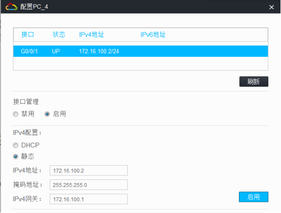
内网2的终端填写IP地址:

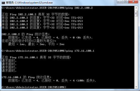
内网1的终端能PING通内网2出口设备的外网地址,但是PING不同内网2的内网地址:

内网2的终端能PING内网1的外网地址,PING不同内网1的内网地址:

第二阶段调试(L2TP配置):
LAC关键配置点:
[LAC]local-user james class network
New local user added.
[LAC-luser-network-james]password simple james
[LAC-luser-network-james]service-type ppp
[LAC-luser-network-james]quit
[LAC]l2tp-group 1 mode lac
[LAC-l2tp1]tunnel name LAC
[LAC-l2tp1]user fullusername james
[LAC-l2tp1]tunnel authentication
[LAC-l2tp1]tunnel password simple james
[LAC-l2tp1]source-ip 202.1.100.2
[LAC-l2tp1]lns-ip 202.2.100.2
[LAC-l2tp1]quit
LAC端发起L2TP链接的关键配置:
[LAC]int Virtual-ppp 1
[LAC-Virtual-PPP1]ip address ppp-negotiate
[LAC-Virtual-PPP1]ppp chap user james
[LAC-Virtual-PPP1]ppp chap password simple james
[LAC-Virtual-PPP1]l2tp-auto-client l2tp-group 1
[LAC-Virtual-PPP1]quit
[LAC]ip route-static 172.16.100.0 255.255.255.0 Virtual-PPP 1 //配置静态路由指向到LNS内部的网段,通过L2TP VPN转发
LNS关键配置点:
[LNS]local-user james class network
New local user added.
[LNS-luser-network-james]password simple james
[LNS-luser-network-james]service-type ppp
[LNS-luser-network-james]quit
[LNS]domain name system
[LNS-isp-system]authentication ppp local
[LNS-isp-system]quit
[LNS]ip pool james 172.16.10.2 172.16.10.250
[LNS]ip pool james gateway 172.16.10.1
[LNS]l2tp enable
[LNS]int Virtual-Template 1
[LNS-Virtual-Template1]ip address 172.16.10.1 255.255.255.0
[LNS-Virtual-Template1]ppp authentication-mode chap domain system
[LNS-Virtual-Template1]remote address pool james
[LNS-Virtual-Template1]quit
[LNS]l2tp-group 1 mode lns
[LNS-l2tp1]tunnel name LNS
[LNS-l2tp1]allow l2tp virtual-template 1 remote LAC
[LNS-l2tp1]tunnel authentication
[LNS-l2tp1]tunnel password simple james
[LNS-l2tp1]quit
第二阶段测试:
分别在LAC和LNS查看L2TP的隧道信息和会话信息:


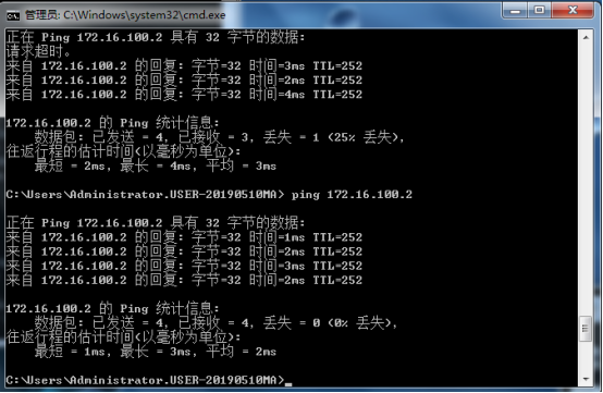
内网1的终端能PING通内网2的终端

因为LAC拨号过来以后使用的是LNS分配的IP地址,所以内网2 PING的是在LNS分配后的IP地址,由于只有一个隧道,因此分配的IP地址为172.16.10.2

至此,L2TP VPN典型组网配置案例2(独立LAC模式)已完成!
- 2021-07-21回答
- 评论(0)
- 举报
-
(0)
暂无评论
编辑答案


亲~登录后才可以操作哦!
确定你的邮箱还未认证,请认证邮箱或绑定手机后进行当前操作
举报
×
侵犯我的权益
×
侵犯了我企业的权益
×
- 1. 您举报的内容是什么?(请在邮件中列出您举报的内容和链接地址)
- 2. 您是谁?(身份证明材料,可以是身份证或护照等证件)
- 3. 是哪家企业?(营业执照,单位登记证明等证件)
- 4. 您与该企业的关系是?(您是企业法人或被授权人,需提供企业委托授权书)
抄袭了我的内容
×
原文链接或出处
诽谤我
×
- 1. 您举报的内容以及侵犯了您什么权益?(请在邮件中列出您举报的内容、链接地址,并给出简短的说明)
- 2. 您是谁?(身份证明材料,可以是身份证或护照等证件)
对根叔社区有害的内容
×
不规范转载
×
举报说明


暂无评论