
问题描述:
2台s6850做irf,网络环境是个大型厂区,用什么什么方式检测mad?求配置和思路,谢谢!
组网及组网描述:
2台s6850做irf,网络环境是个大型厂区,用什么什么方式检测mad?求配置和思路,谢谢!
- 2022-02-18提问
- 举报
-
(0)
最佳答案


如果上联设备时华三的可以直接配置LACP检测:
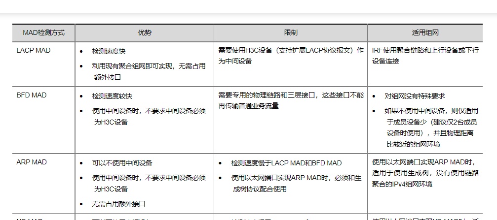
MAD检测机制对比:
配置:
IRF典型配置举例(LACP MAD检测方式)
1. 组网需求
如图1-14所示,配置Device A、Device B、Device C和Device D组成IRF设备。由于IRF到中间设备Device E有跨成员设备的聚合链路,且Device E为支持LACP协议的H3C设备,我们配置LACP MAD进行分裂检测。
2. 组网图
图1-14 IRF典型配置组网图(LACP MAD检测方式)

3. 配置步骤
# 根据图1-14选定IRF物理端口并关闭这些端口。为便于配置,下文中将使用接口批量配置功能关闭和开启物理端口,关于接口批量配置的介绍,请参见“二层技术-以太网交换配置指导”。
[Sysname] interface range hundredgige 1/0/1 to hundredgige 1/0/4
[Sysname-if-range] shutdown
[Sysname-if-range] quit
# 配置IRF端口1/1,并将它与物理端口HundredGigE1/0/1和HundredGigE1/0/2绑定。
[Sysname-irf-port1/1] port group interface hundredgige 1/0/1
[Sysname-irf-port1/1] port group interface hundredgige 1/0/2
[Sysname-irf-port1/1] quit
# 配置IRF端口1/2,并将它与物理端口HundredGigE1/0/3和HundredGigE1/0/4绑定。
[Sysname-irf-port1/2] port group interface hundredgige 1/0/3
[Sysname-irf-port1/2] port group interface hundredgige 1/0/4
[Sysname-irf-port1/2] quit
# 开启HundredGigE1/0/1~HundredGigE1/0/4端口,并保存配置。
[Sysname] interface range hundredgige 1/0/1 to hundredgige 1/0/4
[Sysname-if-range] undo shutdown
[Sysname-if-range] quit
[Sysname] save
# 激活IRF端口下的配置。
[Sysname] irf-port-configuration active
# 将Device B的成员编号配置为2,并重启设备使新编号生效。
[Sysname] irf member 1 renumber 2
Renumbering the member ID may result in configuration change or loss. Continue? [Y/N]:y
[Sysname] quit
<Sysname> reboot
# 重新登录到设备,关闭选定的所有IRF物理端口。
[Sysname] interface range hundredgige 2/0/1 to hundredgige 2/0/4
[Sysname-if-range] shutdown
[Sysname-if-range] quit
# 配置IRF端口2/1,并将它与物理端口HundredGigE2/0/1和HundredGigE2/0/2绑定。
[Sysname-irf-port2/1] port group interface hundredgige 2/0/1
[Sysname-irf-port2/1] port group interface hundredgige 2/0/2
[Sysname-irf-port2/1] quit
# 配置IRF端口2/2,并将它与物理端口HundredGigE2/0/3和HundredGigE2/0/4绑定。
[Sysname-irf-port2/2] port group interface hundredgige 2/0/3
[Sysname-irf-port2/2] port group interface hundredgige 2/0/4
# 开启HundredGigE2/0/1~HundredGigE2/0/4端口,并保存配置。
[Sysname] interface range hundredgige 2/0/1 to hundredgige 2/0/4
[Sysname-if-range] undo shutdown
[Sysname-if-range] quit
[Sysname] save
# 激活IRF端口下的配置。
[Sysname] irf-port-configuration active
(3) Device A和Device B间将会进行主设备竞选,竞选失败的一方将重启,重启完成后,IRF形成。
# 将Device C的成员编号配置为3,并重启设备使新编号生效。
[Sysname] irf member 1 renumber 3
Renumbering the member ID may result in configuration change or loss. Continue? [Y/N]:y
[Sysname] quit
<Sysname> reboot
# 重新登录到设备,关闭选定的所有IRF物理端口。
[Sysname] interface range hundredgige 3/0/1 to hundredgige 3/0/4
[Sysname-if-range] shutdown
[Sysname-if-range] quit
# 配置IRF端口3/1,并将它与物理端口HundredGigE3/0/1和HundredGigE3/0/2绑定。
[Sysname-irf-port3/1] port group interface hundredgige 3/0/1
[Sysname-irf-port3/1] port group interface hundredgige 3/0/2
[Sysname-irf-port3/1] quit
# 配置IRF端口3/2,并将它与物理端口HundredGigE3/0/3和HundredGigE3/0/4绑定。
[Sysname-irf-port3/2] port group interface hundredgige 3/0/3
[Sysname-irf-port3/2] port group interface hundredgige 3/0/4
[Sysname-irf-port3/2] quit
# 开启HundredGigE3/0/1~HundredGigE3/0/4端口,并保存配置。
[Sysname] interface range hundredgige 3/0/1 to hundredgige 3/0/4
[Sysname-if-range] undo shutdown
[Sysname-if-range] quit
[Sysname] save
# 激活IRF端口下的配置。
[Sysname] irf-port-configuration active
(5) Device C将自动重启,加入Device A和Device B已经形成的IRF。
# 将Device D的成员编号配置为4,并重启设备使新编号生效。
[Sysname] irf member 1 renumber 4
Renumbering the member ID may result in configuration change or loss. Continue? [Y/N]:y
[Sysname] quit
<Sysname> reboot
# 重新登录到设备,关闭选定的所有IRF物理端口。
[Sysname] interface range hundredgige 4/0/1 to hundredgige 4/0/4
[Sysname-if-range] shutdown
[Sysname-if-range] quit
# 配置IRF端口4/1,并将它与物理端口HundredGigE4/0/1和HundredGigE4/0/2绑定。
[Sysname-irf-port4/1] port group interface hundredgige 4/0/1
[Sysname-irf-port4/1] port group interface hundredgige 4/0/2
[Sysname-irf-port4/1] quit
# 配置IRF端口4/2,并将它与物理端口HundredGigE4/0/3和HundredGigE4/0/4绑定。
[Sysname-irf-port4/2] port group interface hundredgige 4/0/3
[Sysname-irf-port4/2] port group interface hundredgige 4/0/4
[Sysname-irf-port4/2] quit
# 开启HundredGigE4/0/1~HundredGigE4/0/4端口,并保存配置。
[Sysname] interface range hundredgige 4/0/1 to hundredgige 4/0/4
[Sysname-if-range] undo shutdown
[Sysname-if-range] quit
[Sysname] save
# 激活IRF端口下的配置。
[Sysname] irf-port-configuration active
(7) Device D将自动重启,加入Device A、Device B和Device C已经形成的IRF。
# 设置IRF域编号为1。
[Sysname] irf domain 1
# 创建一个动态聚合接口,并使能LACP MAD检测功能。
[Sysname] interface bridge-aggregation 2
[Sysname-Bridge-Aggregation2] link-aggregation mode dynamic
[Sysname-Bridge-Aggregation2] mad enable
You need to assign a domain ID (range: 0-4294967295)
[Current domain ID is: 1]:
The assigned domain ID is: 1
[Sysname-Bridge-Aggregation2] quit
# 在聚合接口中添加成员端口HundredGigE1/0/5、HundredGigE2/0/5、HundredGigE3/0/5和HundredGigE4/0/5,用于Device A和Device B实现LACP MAD检测。
[Sysname] interface range hundredgige 1/0/5 hundredgige 2/0/5 hundredgige 3/0/5 hundredgige 4/0/5
[Sysname-if-range] port link-aggregation group 2
[Sysname-if-range] quit
Device E作为中间设备来转发、处理LACP协议报文,协助IRF中的四台成员设备进行多Active检测。从节约成本的角度考虑,使用一台支持LACP协议扩展功能的交换机即可。
如果中间设备是一个IRF系统,则必须通过配置确保其IRF域编号与被检测的IRF系统不同。
# 创建一个动态聚合接口。
[Sysname] interface bridge-aggregation 2
[Sysname-Bridge-Aggregation2] link-aggregation mode dynamic
[Sysname-Bridge-Aggregation2] quit
# 在聚合接口中添加成员端口HundredGigE1/0/1~HundredGigE1/0/4,用于帮助LACP MAD检测。
[Sysname] interface range hundredgige 1/0/1 to hundredgige 1/0/4
[Sysname-if-range] port link-aggregation group 2
[Sysname-if-range] quit
MAD检测:
IRF典型配置举例(VLAN接口配置BFD MAD检测方式)
1. 组网需求
如图1-15所示,配置Device A、Device B、Device C和Device D组成IRF设备。配置BFD MAD进行分裂检测。
2. 组网图
图1-15 IRF典型配置组网图(BFD MAD检测方式)

3. 配置步骤
(1) 配置Device A
[Sysname] interface range hundredgige 1/0/1 to hundredgige 1/0/4
[Sysname-if-range] shutdown
[Sysname-if-range] quit
# 配置IRF端口1/1,并将它与物理端口HundredGigE1/0/1和HundredGigE1/0/2绑定。
[Sysname-irf-port1/1] port group interface hundredgige 1/0/1
[Sysname-irf-port1/1] port group interface hundredgige 1/0/2
[Sysname-irf-port1/1] quit
# 配置IRF端口1/2,并将它与物理端口HundredGigE1/0/3和HundredGigE1/0/4绑定。
[Sysname-irf-port1/2] port group interface hundredgige 1/0/3
[Sysname-irf-port1/2] port group interface hundredgige 1/0/4
[Sysname-irf-port1/2] quit
# 开启HundredGigE1/0/1~HundredGigE1/0/4端口,并保存配置。
[Sysname] interface range hundredgige 1/0/1 to hundredgige 1/0/4
[Sysname-if-range] undo shutdown
[Sysname-if-range] quit
[Sysname] save
# 激活IRF端口下的配置。
[Sysname] irf-port-configuration active
# 将Device B的成员编号配置为2,并重启设备使新编号生效。
[Sysname] irf member 1 renumber 2
Renumbering the member ID may result in configuration change or loss. Continue? [Y/N]:y
[Sysname] quit
<Sysname> reboot
# 重新登录到设备,关闭选定的所有IRF物理端口。
[Sysname] interface range hundredgige 2/0/1 to hundredgige 2/0/4
[Sysname-if-range] shutdown
[Sysname-if-range] quit
# 配置IRF端口2/1,并将它与物理端口HundredGigE2/0/1和HundredGigE2/0/2绑定。
[Sysname-irf-port2/1] port group interface hundredgige 2/0/1
[Sysname-irf-port2/1] port group interface hundredgige 2/0/2
[Sysname-irf-port2/1] quit
# 配置IRF端口2/2,并将它与物理端口HundredGigE2/0/3和HundredGigE2/0/4绑定。
[Sysname-irf-port2/2] port group interface hundredgige 2/0/3
[Sysname-irf-port2/2] port group interface hundredgige 2/0/4
# 开启HundredGigE2/0/1~HundredGigE2/0/4端口,并保存配置。
[Sysname] interface range hundredgige 2/0/1 to hundredgige 2/0/4
[Sysname-if-range] undo shutdown
[Sysname-if-range] quit
[Sysname] save
# 激活IRF端口下的配置。
[Sysname] irf-port-configuration active
(3) Device A和Device B间将会进行主设备竞选,竞选失败的一方将重启,重启完成后,IRF形成。
# 将Device C的成员编号配置为3,并重启设备使新编号生效。
[Sysname] irf member 1 renumber 3
Renumbering the member ID may result in configuration change or loss. Continue? [Y/N]:y
[Sysname] quit
<Sysname> reboot
# 重新登录到设备,关闭选定的所有IRF物理端口。
[Sysname] interface range hundredgige 3/0/1 to hundredgige 3/0/4
[Sysname-if-range] shutdown
[Sysname-if-range] quit
# 配置IRF端口3/1,并将它与物理端口HundredGigE3/0/1和HundredGigE3/0/2绑定。
[Sysname-irf-port3/1] port group interface hundredgige 3/0/1
[Sysname-irf-port3/1] port group interface hundredgige 3/0/2
[Sysname-irf-port3/1] quit
# 配置IRF端口3/2,并将它与物理端口HundredGigE3/0/3和HundredGigE3/0/4绑定。
[Sysname-irf-port3/2] port group interface hundredgige 3/0/3
[Sysname-irf-port3/2] port group interface hundredgige 3/0/4
[Sysname-irf-port3/2] quit
# 开启HundredGigE3/0/1~HundredGigE3/0/4端口,并保存配置。
[Sysname] interface range hundredgige 3/0/1 to hundredgige 3/0/4
[Sysname-if-range] undo shutdown
[Sysname-if-range] quit
[Sysname] save
# 激活IRF端口下的配置。
[Sysname] irf-port-configuration active
(5) Device C将自动重启,加入Device A和Device B已经形成的IRF。
# 将Device D的成员编号配置为4,并重启设备使新编号生效。
[Sysname] irf member 1 renumber 4
Renumbering the member ID may result in configuration change or loss. Continue? [Y/N]:y
[Sysname] quit
<Sysname> reboot
# 重新登录到设备,关闭选定的所有IRF物理端口。
[Sysname] interface range hundredgige 4/0/1 to hundredgige 4/0/4
[Sysname-if-range] shutdown
[Sysname-if-range] quit
# 配置IRF端口4/1,并将它与物理端口HundredGigE4/0/1和HundredGigE4/0/2绑定。
[Sysname-irf-port4/1] port group interface hundredgige 4/0/1
[Sysname-irf-port4/1] port group interface hundredgige 4/0/2
[Sysname-irf-port4/1] quit
# 配置IRF端口4/2,并将它与物理端口HundredGigE4/0/3和HundredGigE4/0/4绑定。
[Sysname-irf-port4/2] port group interface hundredgige 4/0/3
[Sysname-irf-port4/2] port group interface hundredgige 4/0/4
[Sysname-irf-port4/2] quit
# 开启HundredGigE4/0/1~HundredGigE4/0/4端口,并保存配置。
[Sysname] interface range hundredgige 4/0/1 to hundredgige 4/0/4
[Sysname-if-range] undo shutdown
[Sysname-if-range] quit
[Sysname] save
# 激活IRF端口下的配置。
[Sysname] irf-port-configuration active
(7) Device D将自动重启,加入Device A、Device B和Device C已经形成的IRF。
# 创建VLAN 3,并将端口HundredGigE1/0/5、HundredGigE2/0/5、HundredGigE3/0/5和HundredGigE4/0/5加入VLAN 3中。
[Sysname-vlan3] port hundredgige 1/0/5 hundredgige 2/0/5 hundredgige 3/0/5 hundredgige 4/0/5
[Sysname-vlan3] quit
# 创建VLAN接口3,并配置MAD IP地址。
[Sysname] interface vlan-interface 3
[Sysname-Vlan-interface3] mad bfd enable
[Sysname-Vlan-interface3] mad ip address 192.168.2.1 24 member 1
[Sysname-Vlan-interface3] mad ip address 192.168.2.2 24 member 2
[Sysname-Vlan-interface3] mad ip address 192.168.2.3 24 member 3
[Sysname-Vlan-interface3] mad ip address 192.168.2.4 24 member 4
[Sysname-Vlan-interface3] quit
# 因为BFD MAD和生成树功能互斥,所以在HundredGigE1/0/5、HundredGigE2/0/5、HundredGigE3/0/5和HundredGigE4/0/5端口上关闭生成树协议。
[Sysname] interface range hundredgige 1/0/5 hundredgige 2/0/5 hundredgige 3/0/5 hundredgige 4/0/5
[Sysname-if-range] undo stp enable
[Sysname-if-range] quit
Device E作为中间设备来透传BFD MAD报文,协助IRF中的四台成员设备进行多Active检测。
# 创建VLAN 3,并将端口HundredGigE1/0/1~HundredGigE1/0/4加入VLAN 3中,用于转发BFD MAD报文。
[DeviceE] vlan 3
[DeviceE-vlan3] port hundredgige 1/0/1 to hundredgige 1/0/4
[DeviceE-vlan3] quit
1.9.3 IRF典型配置举例(VLAN接口配置ARP MAD检测方式)
1. 组网需求
如图1-16所示,配置Device A、Device B、Device C和Device D组成IRF设备。配置ARP MAD进行分裂检测。为防止环路发生,在IRF和Device E上启用生成树功能。
2. 组网图
图1-16 IRF典型配置组网图(ARP MAD检测方式)

3. 配置步骤
(1) 配置Device A
[Sysname] interface range hundredgige 1/0/1 to hundredgige 1/0/4
[Sysname-if-range] shutdown
[Sysname-if-range] quit
# 配置IRF端口1/1,并将它与物理端口HundredGigE1/0/1和HundredGigE1/0/2绑定。
[Sysname-irf-port1/1] port group interface hundredgige 1/0/1
[Sysname-irf-port1/1] port group interface hundredgige 1/0/2
[Sysname-irf-port1/1] quit
# 配置IRF端口1/2,并将它与物理端口HundredGigE1/0/3和HundredGigE1/0/4绑定。
[Sysname-irf-port1/2] port group interface hundredgige 1/0/3
[Sysname-irf-port1/2] port group interface hundredgige 1/0/4
[Sysname-irf-port1/2] quit
# 开启HundredGigE1/0/1~HundredGigE1/0/4端口,并保存配置。
[Sysname] interface range hundredgige 1/0/1 to hundredgige 1/0/4
[Sysname-if-range] undo shutdown
[Sysname-if-range] quit
[Sysname] save
# 激活IRF端口下的配置。
[Sysname] irf-port-configuration active
# 将Device B的成员编号配置为2,并重启设备使新编号生效。
[Sysname] irf member 1 renumber 2
Renumbering the member ID may result in configuration change or loss. Continue? [Y/N]:y
[Sysname] quit
<Sysname> reboot
# 重新登录到设备,关闭选定的所有IRF物理端口。
[Sysname] interface range hundredgige 2/0/1 to hundredgige 2/0/4
[Sysname-if-range] shutdown
[Sysname-if-range] quit
# 配置IRF端口2/1,并将它与物理端口HundredGigE2/0/1和HundredGigE2/0/2绑定。
[Sysname-irf-port2/1] port group interface hundredgige 2/0/1
[Sysname-irf-port2/1] port group interface hundredgige 2/0/2
[Sysname-irf-port2/1] quit
# 配置IRF端口2/2,并将它与物理端口HundredGigE2/0/3和HundredGigE2/0/4绑定。
[Sysname-irf-port2/2] port group interface hundredgige 2/0/3
[Sysname-irf-port2/2] port group interface hundredgige 2/0/4
# 开启HundredGigE2/0/1~HundredGigE2/0/4端口,并保存配置。
[Sysname] interface range hundredgige 2/0/1 to hundredgige 2/0/4
[Sysname-if-range] undo shutdown
[Sysname-if-range] quit
[Sysname] save
# 激活IRF端口下的配置。
[Sysname] irf-port-configuration active
(3) Device A和Device B间将会进行主设备竞选,竞选失败的一方将重启,重启完成后,IRF形成。
# 将Device C的成员编号配置为3,并重启设备使新编号生效。
[Sysname] irf member 1 renumber 3
Renumbering the member ID may result in configuration change or loss. Continue? [Y/N]:y
[Sysname] quit
<Sysname> reboot
# 重新登录到设备,关闭选定的所有IRF物理端口。
[Sysname] interface range hundredgige 3/0/1 to hundredgige 3/0/4
[Sysname-if-range] shutdown
[Sysname-if-range] quit
# 配置IRF端口3/1,并将它与物理端口HundredGigE3/0/1和HundredGigE3/0/2绑定。
[Sysname-irf-port3/1] port group interface hundredgige 3/0/1
[Sysname-irf-port3/1] port group interface hundredgige 3/0/2
[Sysname-irf-port3/1] quit
# 配置IRF端口3/2,并将它与物理端口HundredGigE3/0/3和HundredGigE3/0/4绑定。
[Sysname-irf-port3/2] port group interface hundredgige 3/0/3
[Sysname-irf-port3/2] port group interface hundredgige 3/0/4
[Sysname-irf-port3/2] quit
# 开启HundredGigE3/0/1~HundredGigE3/0/4端口,并保存配置。
[Sysname] interface range hundredgige 3/0/1 to hundredgige 3/0/4
[Sysname-if-range] undo shutdown
[Sysname-if-range] quit
[Sysname] save
# 激活IRF端口下的配置。
[Sysname] irf-port-configuration active
(5) Device C将自动重启,加入Device A和Device B已经形成的IRF。
# 将Device D的成员编号配置为4,并重启设备使新编号生效。
[Sysname] irf member 1 renumber 4
Renumbering the member ID may result in configuration change or loss. Continue? [Y/N]:y
[Sysname] quit
<Sysname> reboot
# 重新登录到设备,关闭选定的所有IRF物理端口。
[Sysname] interface range hundredgige 4/0/1 to hundredgige 4/0/4
[Sysname-if-range] shutdown
[Sysname-if-range] quit
# 配置IRF端口4/1,并将它与物理端口HundredGigE4/0/1和HundredGigE4/0/2绑定。
[Sysname-irf-port4/1] port group interface hundredgige 4/0/1
[Sysname-irf-port4/1] port group interface hundredgige 4/0/2
[Sysname-irf-port4/1] quit
# 配置IRF端口4/2,并将它与物理端口HundredGigE4/0/3和HundredGigE4/0/4绑定。
[Sysname-irf-port4/2] port group interface hundredgige 4/0/3
[Sysname-irf-port4/2] port group interface hundredgige 4/0/4
[Sysname-irf-port4/2] quit
# 开启HundredGigE4/0/1~HundredGigE4/0/4端口,并保存配置。
[Sysname] interface range hundredgige 4/0/1 to hundredgige 4/0/4
[Sysname-if-range] undo shutdown
[Sysname-if-range] quit
[Sysname] save
# 激活IRF端口下的配置。
[Sysname] irf-port-configuration active
(7) Device D将自动重启,加入Device A、Device B和Device C已经形成的IRF。
# 在IRF上全局使能生成树协议,并配置MST域,以防止环路的发生。
[Sysname] stp global enable
[Sysname] stp region-configuration
[Sysname-mst-region] region-name arpmad
[Sysname-mst-region] instance 1 vlan 3
[Sysname-mst-region] active region-configuration
# 将IRF配置为桥MAC立即改变。
[Sysname] undo irf mac-address persistent
# 设置IRF域编号为1。
# 创建VLAN 3,并将端口HundredGigE1/0/5、HundredGigE2/0/5、HundredGigE3/0/5和HundredGigE4/0/5加入VLAN 3中。
[Sysname-vlan3] port hundredgige 1/0/5 hundredgige 2/0/5 hundredgige 3/0/5 hundredgige 4/0/5
[Sysname-vlan3] quit
# 创建VLAN-interface3,并配置IP地址,使能ARP MAD检测功能。
[Sysname] interface vlan-interface 3
[Sysname-Vlan-interface3] ip address 192.168.2.1 24
[Sysname-Vlan-interface3] mad arp enable
You need to assign a domain ID (range: 0-4294967295)
[Current domain ID is: 1]:
The assigned domain ID is: 1
Device E作为中间设备来转发、处理ARP报文,协助IRF中的四台成员设备进行多Active检测。从节约成本的角度考虑,使用一台支持ARP功能的交换机即可。
如果中间设备是一个IRF系统,则必须通过配置确保其IRF域编号与被检测的IRF系统不同。
# 在全局使能生成树协议,并配置MST域,以防止环路的发生。
[DeviceE] stp global enable
[DeviceE] stp region-configuration
[DeviceE-mst-region] region-name arpmad
[DeviceE-mst-region] instance 1 vlan 3
[DeviceE-mst-region] active region-configuration
# 创建VLAN 3,并将端口HundredGigE1/0/1~HundredGigE1/0/4加入VLAN 3中,用于转发ARP MAD报文。
[DeviceE-vlan3] port hundredgige 1/0/1 to hundredgige 1/0/4
[DeviceE-vlan3] quit
ARP检测:
管理用以太网口配置ARP MAD典型配置举例(管理功能和MAD功能配置在同一接口)
![]()
· 本节介绍使用管理用以太网口配置ARP MAD,同时不影响网络管理功能使用的配置举例。并且,IRF分裂后,用户可以分别登录到分裂出的IRF上以便进行故障修复。
· 本举例也适用于ND MAD。仅MAD部分采用相应的配置方法即可。MAD的详细配置方法请参考配置指导。
1. 组网需求
如图1-18所示,Device A和Device B组成IRF。现要求:
· 使用管理用以太网口M-GigabitEthernet0/0/0配置ARP MAD进行分裂检测,同时不影响网络管理功能的使用;
· IRF主备倒换后,管理员登录用的IP地址不能变化;
· IRF分裂后,允许管理员分别登录到分裂出的成员设备上以进行故障恢复。
图1-18 管理用以太网口配置ARP MAD典型配置举例

2. 配置思路
主设备管理用以太网接口需要进行如下IP地址配置:
· 使用ip address ip-address { mask-length | mask }命令配置IRF的管理用IP地址。IRF未分裂时请通过此地址登录IRF。IRF发生主备倒换时不影响管理员通过此地址登录IRF。
· 使用ip address ip-address { mask-length | mask } irf-member member-id命令分别配置各成员设备的IP地址。IRF分裂后,管理员可以通过成员设备的IP地址分别登录到分裂出的成员设备上以进行故障恢复。
3. 配置注意事项
配置IRF成员设备的IP地址时请注意:
· 同一个管理用以太网接口下配置的所有IRF成员设备的管理用以太网接口地址必须处于同一网段,不同的管理用以太网接口下配置的IRF成员设备的管理用以太网接口地址不能在同一网段。
· 当IRF正常工作时,只有主设备的管理用以太网接口地址生效,从设备的管理用以太网接口地址不生效。如果从设备管理用以太网接口地址与网络中其他设备地址冲突,并不会打印冲突信息,所以需要用户保证配置的管理用以太网接口地址不会冲突。
IRF分裂后,由于分裂出的IRF的管理用以太网接口上均存在ip address ip-address { mask-length | mask }命令配置的IP地址,设备会上报地址冲突,但不影响管理员使用ip address ip-address { mask-length | mask } irf-member member-id命令配置的IP地址分别登录分裂出的IRF设备。
配置ARP MAD时请注意,如果中间设备是一个IRF系统,则必须通过配置确保其IRF域编号与被检测的IRF系统不同。
4. 配置步骤
(1) 配置IRF
a. 配置Device A
# 将用作IRF物理端口的HundredGigE1/0/25~HundredGigE1/0/26的手工关闭。使用端口批量配置功能可以更快速的完成配置。
<DeviceA> system-view
[DeviceA] interface range hundredgige 1/0/25 to hundredgige 1/0/26
[DeviceA-if-range] shutdown
[DeviceA-if-range] quit
# 创建IRF端口2,与端口HundredGigE1/025和HundredGigE1/0/26绑定。
[DeviceA] irf-port 1/2
[DeviceA-irf-port1/2] port group interface hundredgige 1/0/25
[DeviceA-irf-port1/2] port group interface hundredgige 1/0/26
[DeviceA-irf-port1/2] quit
# 开启HundredGigE1/0/25~HundredGigE1/0/26端口。
[DeviceA] interface range hundredgige 1/0/25 to hundredgige 1/0/26
[DeviceA-if-range] undo shutdown
[DeviceA-if-range] quit
# 将当前配置保存到下次启动配置文件。
[DeviceA] quit
<DeviceA> save
# 激活IRF端口的配置。
<DeviceA> system-view
[DeviceA] irf-port-configuration active
b. 配置Device B
# 配置Device B的成员编号为2,并重启设备使配置生效。
<DeviceB> system-view
[DeviceB] irf member 1 renumber 2
Renumbering the member ID may result in configuration change or loss. Continue? [Y/N]:y
[DeviceB] quit
<DeviceB> reboot
# 将用作IRF物理端口的HundredGigE2/0/25~HundredGigE2/0/26的手工关闭。使用端口批量配置功能可以更快速的完成配置。
<DeviceB> system-view
[DeviceB] interface range hundredgige 2/0/25 to hundredgige 2/0/26
[DeviceB-if-range] shutdown
[DeviceB-if-range] quit
# 创建IRF端口1,与端口HundredGigE2/0/25和HundredGigE2/0/26绑定。
[DeviceB] irf-port 2/1
[DeviceB-irf-port2/1] port group interface hundredgige 2/0/25
[DeviceB-irf-port2/1] port group interface hundredgige 2/0/26
[DeviceB-irf-port2/1] quit
# 开启HundredGigE2/0/25~HundredGigE2/0/26端口。
[DeviceB] interface range hundredgige 2/0/25 to hundredgige 2/0/26
[DeviceB-if-range] undo shutdown
[DeviceB-if-range] quit
# 将当前配置保存到下次启动配置文件。
[DeviceB] quit
<DeviceB> save
# 参照图1-18连接DeviceB和DeviceA。
# 激活IRF端口的配置。
<DeviceB> system-view
[DeviceB] irf-port-configuration active
# 系统会提示发生IRF合并,竞选失败的设备重启后两台设备形成一个IRF。
(2) 配置管理IP
# 在M-GigabitEthernet0/0/0接口上,配置IRF正常工作时,管理员登录IRF使用的IP地址192.168.1.1。
<IRF> system-view
[IRF] interface m-gigabitethernet 0/0/0
[IRF-M-GigabitEthernet0/0/0] ip address 192.168.1.1 24
# 在M-GigabitEthernet0/0/0接口上,分别配置IRF成员设备1和成员设备2的IP地址为192.168.1.101/24和192.168.1.102/24。如果IRF分裂,管理员可以使用192.168.1.101和192.168.1.102分别登录到成员设备1和成员设备2上。
[IRF-M-GigabitEthernet0/0/0] ip address 192.168.1.101 24 irf-member 1
[IRF-M-GigabitEthernet0/0/0] ip address 192.168.1.102 24 irf-member 2
[IRF-M-GigabitEthernet0/0/0] quit
# 配置M-GigabitEthernet0/0/0为MAD保留接口,以使IRF分裂后M-GigabitEthernet0/0/0不会被MAD功能关闭。
[IRF] mad exclude interface m-gigabitethernet 0/0/0
(3) 配置ARP MAD
a. 配置IRF
# IRF的桥MAC保留时间配置为立即改变。
[IRF] undo irf mac-address persistent
# 配置IRF域编号为1。
[IRF] irf domain 1
# 开启管理用以太网接口M-GigabitEthernet0/0/0的ARP MAD检测功能。
[IRF-M-GigabitEthernet0/0/0] mad arp enable
You need to assign a domain ID (range: 0-4294967295)
[Current domain ID is: 1]:
The assigned domain ID is: 1
[IRF-M-GigabitEthernet0/0/0] quit
# 将当前配置保存到下次启动配置文件。
[IRF] save
b. 配置中间设备Device C
# 创建VLAN 100,并将端口GigabitEthernet1/0/1~GigabitEthernet1/0/2加入VLAN 100中,用于转发ARP MAD报文。
[DeviceC] vlan 100
[DeviceC-vlan100] port gigabitethernet 1/0/1 to gigabitethernet 1/0/4
[DeviceC-vlan100] quit
5. 验证配置
(1) 断开Device A和Device B之间的IRF物理链路后,可以分别使用192.168.1.101和192.168.1.102登录到Device A和Device B上。
(2) 在Device A和Device B上分别执行display mad verbose命令,可以看到一台设备Multi-active recovery state为Yes,使用display interface brief命令可以看到这台设备所有的端口处于down状态(除了IRF物理端口和管理用以太网接口M-GigabitEthernet0/0/0)。另一台设备Multi-active recovery state为No,正常工作。
1.9.6 管理用以太网口配置BFD MAD典型配置举例(管理功能和MAD功能配置在不同接口)
![]()
· 本节介绍双管理用以太网接口设备,一个管理用以太网口配置BFD MAD,另一个管理用以太网口承担网络管理功能的配置举例。并且,IRF分裂后,用户可以分别登录到分裂出的IRF上以便进行故障修复。
· 本举例也适用于ARP MAD和ND MAD。仅MAD部分采用相应的配置方法即可。MAD的详细配置方法请参考配置指导。
1. 组网需求
如图1-19所示,Device A和Device B组成IRF。现要求:
· 使用管理用以太网口M-GigabitEthernet0/0/0接入管理网络;
· 使用管理用以太网口M-GigabitEthernet0/0/1配置BFD MAD进行分裂检测;
· IRF主备倒换后,管理员登录用的IP地址不能变化;
· IRF分裂后,允许管理员分别登录到分裂出的成员设备上以进行故障恢复。
图1-19 管理用以太网口配置BFD MAD典型配置举例

2. 配置思路
主设备管理用以太网接口M-GigabitEthernet0/0/0需要进行如下IP地址配置:
· 使用ip address ip-address { mask-length | mask }命令配置IRF的管理用IP地址。IRF未分裂时请通过此地址登录IRF。IRF发生主备倒换时不影响管理员通过此地址登录IRF。
· 使用ip address ip-address { mask-length | mask } irf-member member-id命令分别配置各成员设备的IP地址。IRF分裂后,管理员可以通过成员设备的IP地址分别登录到分裂出的成员设备上以进行故障恢复。
3. 配置注意事项
配置IRF成员设备的IP地址时请注意:
· 同一个管理用以太网接口下配置的所有IRF成员设备的管理用以太网接口地址必须处于同一网段,不同的管理用以太网接口下配置的IRF成员设备的管理用以太网接口地址不能在同一网段。
· 当IRF正常工作时,只有主设备的管理用以太网接口地址生效,从设备的管理用以太网接口地址不生效。如果从设备管理用以太网接口地址与网络中其他设备地址冲突,并不会打印冲突信息,所以需要用户保证配置的管理用以太网接口地址不会冲突。
IRF分裂后,由于分裂出的IRF的管理用以太网接口上均存在ip address ip-address { mask-length | mask }命令配置的IP地址,设备会上报地址冲突,但不影响管理员使用ip address ip-address { mask-length | mask } irf-member member-id命令配置的IP地址分别登录分裂出的IRF设备。
配置BFD MAD时请注意,
· 请确保中间设备上BFD MAD检测VLAN中仅包含用于BFD MAD检测的端口。
· 在用于BFD MAD检测的接口下必须使用mad ip address命令配置MAD IP地址,而不要配置其它IP地址(包括使用ip address命令配置的普通IP地址、VRRP虚拟IP地址等),以免影响MAD检测功能。请为不同成员设备配置同一网段内的不同MAD IP地址。
4. 配置步骤
(1) 配置IRF
a. 配置Device A
# 将用作IRF物理端口的HundredGigE1/0/25~HundredGigE1/0/26的手工关闭。使用端口批量配置功能可以更快速的完成配置。
<DeviceA> system-view
[DeviceA] interface range hundredgige 1/0/25 to hundredgige 1/0/26
[DeviceA-if-range] shutdown
[DeviceA-if-range] quit
# 创建IRF端口2,与端口HundredGigE1/025和HundredGigE1/0/26绑定。
[DeviceA] irf-port 1/2
[DeviceA-irf-port1/2] port group interface hundredgige 1/0/25
[DeviceA-irf-port1/2] port group interface hundredgige 1/0/26
[DeviceA-irf-port1/2] quit
# 开启HundredGigE1/0/25~HundredGigE1/0/26端口。
[DeviceA] interface range hundredgige 1/0/25 to hundredgige 1/0/26
[DeviceA-if-range] undo shutdown
[DeviceA-if-range] quit
# 将当前配置保存到下次启动配置文件。
[DeviceA] quit
<DeviceA> save
# 激活IRF端口的配置。
<DeviceA> system-view
[DeviceA] irf-port-configuration active
b. 配置Device B
# 配置Device B的成员编号为2,并重启设备使配置生效。
<DeviceB> system-view
[DeviceB] irf member 1 renumber 2
Renumbering the member ID may result in configuration change or loss. Continue? [Y/N]:y
[DeviceB] quit
<DeviceB> reboot
# 将用作IRF物理端口的HundredGigE2/0/25~HundredGigE2/0/26的手工关闭。使用端口批量配置功能可以更快速的完成配置。
<DeviceB> system-view
[DeviceB] interface range hundredgige 2/0/25 to hundredgige 2/0/26
[DeviceB-if-range] shutdown
[DeviceB-if-range] quit
# 创建IRF端口1,与端口HundredGigE2/0/25和HundredGigE2/0/26绑定。
[DeviceB] irf-port 2/1
[DeviceB-irf-port2/1] port group interface hundredgige 2/0/25
[DeviceB-irf-port2/1] port group interface hundredgige 2/0/26
[DeviceB-irf-port2/1] quit
# 开启HundredGigE2/0/25~HundredGigE2/0/26端口。
[DeviceB] interface range hundredgige 2/0/25 to hundredgige 2/0/26
[DeviceB-if-range] undo shutdown
[DeviceB-if-range] quit
# 将当前配置保存到下次启动配置文件。
[DeviceB] quit
<DeviceB> save
# 参照图1-18连接DeviceB和DeviceA。
# 激活IRF端口的配置。
<DeviceB> system-view
[DeviceB] irf-port-configuration active
# 系统会提示发生IRF合并,竞选失败的设备重启后两台设备形成一个IRF。
(2) 配置管理IP
# 在M-GigabitEthernet0/0/0接口上,配置IRF正常工作时,管理员登录IRF使用的IP地址192.168.1.1。
<IRF> system-view
[IRF] interface m-gigabitethernet 0/0/0
[IRF-M-GigabitEthernet0/0/0] ip address 192.168.1.1 24
# 在M-GigabitEthernet0/0/0接口上,分别配置IRF成员设备1和成员设备2的IP地址为192.168.1.101/24和192.168.1.102/24。如果IRF分裂,管理员可以使用192.168.1.101和192.168.1.102分别登录到成员设备1和成员设备2上。
[IRF-M-GigabitEthernet0/0/0] ip address 192.168.1.101 24 irf-member 1
[IRF-M-GigabitEthernet0/0/0] ip address 192.168.1.102 24 irf-member 2
[IRF-M-GigabitEthernet0/0/0] quit
# 配置IRF成员设备的管理用以太网接口M-GigabitEthernet0/0/0为MAD保留接口,以使IRF分裂后M-GigabitEthernet0/0/0不会被MAD功能关闭。
[IRF] mad exclude interface m-gigabitethernet 0/0/0
(3) 配置BFD MAD
a. 配置IRF
# 配置管理用以太网接口M-GigabitEthernet0/0/1的MAD IP地址。
[IRF] interface m-gigabitethernet 0/0/1
[IRF-M-GigabitEthernet0/0/1] mad ip address 192.168.2.1 24 member 1
[IRF-M-GigabitEthernet0/0/1] mad ip address 192.168.2.2 24 member 2
# 开启管理用以太网接口M-GigabitEthernet0/0/1的BFD MAD检测功能。
[IRF-M-GigabitEthernet0/0/1] mad bfd enable
[IRF-M-GigabitEthernet0/0/0] quit
# 将当前配置保存到下次启动配置文件。
[IRF] save
b. 配置中间设备Device C
# 创建VLAN 100,并将端口GigabitEthernet1/0/1~GigabitEthernet1/0/2加入VLAN 100中,用于转发BFD MAD报文。
[DeviceC] vlan 100
[DeviceC-vlan100] port gigabitethernet 1/0/1 to gigabitethernet 1/0/4
[DeviceC-vlan100] quit
5. 验证配置
(1) 断开Device A和Device B之间的IRF物理链路后,可以分别使用192.168.1.101和192.168.1.102登录到Device A和Device B上。
(2) 在Device A和Device B上分别执行display mad verbose命令,可以看到一台设备Multi-active recovery state为Yes,使用display interface brief命令可以看到这台设备所有的端口处于down状态(除了IRF物理端口和管理用以太网接口M-GigabitEthernet0/0/0、M-GigabitEthernet0/0/1)。另一台设备Multi-active recovery state为No,正常工作。
- 2022-02-18回答
- 评论(2)
- 举报
-
(0)
你好!我误区在这个irf,irf配置怎么区分核心和汇聚?
是这样的,一般核心区域的话是所有网段的网关所在的设备,而汇聚一般就是起到接入层的接入层上连线汇聚的作用,当然看网络规模,有些网络是接入直接连核心,中间没有汇聚层。或者还有种情况就是超大型园区网络,比如每栋楼都有20个网段,那么可能20个网段的地址网关配置在汇聚上,所有接入连接汇聚,然后每栋楼的汇聚再连接核心,因为每栋楼都需要互访,那么就需要通过核心设备来打通各个楼栋的路由

3.12 IRF典型配置举例
3.12.1 IRF典型配置举例(LACP MAD检测方式)
1. 组网需求
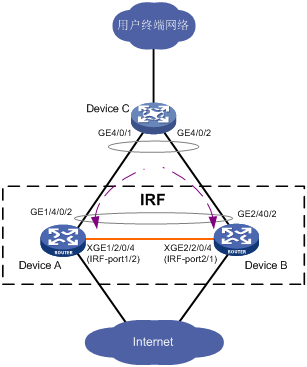
为提高网络出口可靠性,使用Device A、Device B做为内网出口设备,为便于对设备Device A与Device B易管理、易维护。使用IRF技术,并使用LACP MAD功能及时发现和处理IRF的分裂事件。
2. 组网图
图3-13 IRF典型配置组网图(LACP MAD检测方式)
3. 配置思路
· 鉴于第二代智能弹性架构IRF技术具有管理简便、网络扩展能力强、可靠性高等优点,所以本例使用IRF技术构建接入层(即在Device A和Device B上配置IRF功能)。
· 为了防止万一IRF链路故障导致IRF分裂、网络中存在两个配置冲突的IRF,需要启用MAD检测功能。因为接入层设备较多,我们采用LACP MAD检测。
4. 配置步骤
# 配置Device A的成员编号为1,创建IRF端口2,并将它与物理端口Ten-GigabitEthernet2/0/4绑定。
[Sysname] irf member 1
Info: Member ID change will take effect after the member reboots and operates in IRF mode.
[Sysname] irf-port 2
[Sysname-irf-port2] port group interface ten-gigabitethernet 2/0/4
[Sysname-irf-port2] quit
# 将当前配置保存到下次启动配置文件。
<Sysname> save
# 将设备的运行模式切换到IRF模式。
[Sysname] chassis convert mode irf
The device will switch to IRF mode and reboot. You are recommended to save the current running configuration and specify the configuration file for the next startup. Continue? [Y/N]:y
Do you want to convert the content of the next startup configuration file flash:/startup.cfg to make it available in IRF mode? [Y/N]:y
Please wait...
Saving the converted configuration file to the main board succeeded.
Slot 1:
Saving the converted configuration file succeeded.
Now rebooting, please wait...
设备重启后Device A组成了只有一台成员设备的IRF。
# 配置Device B的成员编号为2,创建IRF端口1,并将它与物理端口Ten-GigabitEthernet2/0/4绑定。
[Sysname] irf member 2
Info: Member ID change will take effect after the member reboots and operates in IRF mode.
[Sysname] irf-port 1
[Sysname-irf-port1] port group interface ten-gigabitethernet 2/0/4
[Sysname-irf-port1] quit
# 将当前配置保存到下次启动配置文件。
<Sysname> save
# 将设备的运行模式切换到IRF模式。
[Sysname] chassis convert mode irf
The device will switch to IRF mode and reboot. You are recommended to save the current running configuration and specify the configuration file for the next startup. Continue? [Y/N]:y
Do you want to convert the content of the next startup configuration file flash:/startup.cfg to make it available in IRF mode? [Y/N]:y
Please wait...
Saving the converted configuration file to the main board succeeded.
Slot 1:
Saving the converted configuration file succeeded.
Now rebooting, please wait...
设备B重启后与设备A形成IRF。
# 设置IRF域编号为1。
[Sysname] irf domain 1
# 创建一个动态聚合接口,并使能LACP MAD检测功能。
[Sysname] interface bridge-aggregation 2
[Sysname-Bridge-Aggregation2] link-aggregation mode dynamic
[Sysname-Bridge-Aggregation2] mad enable
You need to assign a domain ID (range: 0-4294967295)
[Current domain is: 1]:
The assigned domain ID is: 1
MAD LACP only enable on dynamic aggregation interface.
[Sysname-Bridge-Aggregation2] quit
# 在聚合接口中添加成员端口1/2/0/4和2/2/0/4,专用于Device A和Device B实现LACP MAD检测。
[Sysname] interface gigabitethernet 1/2/0/4
[Sysname-GigabitEthernet1/2/0/4] port link-aggregation group 2
[Sysname-GigabitEthernet1/2/0/4] quit
[Sysname] interface gigabitethernet 1/2/0/4
[Sysname-GigabitEthernet1/2/0/4] port link-aggregation group 2
![]()
如果中间设备是一个IRF系统,则必须通过配置确保其IRF域编号与被检测的IRF系统不同。
Device C作为中间设备来转发、处理LACP协议报文,协助Device A和Device B进行多Active检测。从节约成本的角度考虑,使用一台支持LACP协议扩展功能的设备即可。
# 创建一个动态聚合接口。
[Sysname] interface bridge-aggregation 2
[Sysname-Bridge-Aggregation2] link-aggregation mode dynamic
[Sysname-Bridge-Aggregation2] quit
# 在聚合接口中添加成员端口GigabitEthernet4/0/1和GigabitEthernet4/0/2,用于帮助LACP MAD检测。
[Sysname] interface gigabitethernet 4/0/1
[Sysname-GigabitEthernet4/0/1] port link-aggregation group 2
[Sysname-GigabitEthernet4/0/1] quit
[Sysname] interface gigabitethernet 4/0/2
[Sysname-GigabitEthernet4/0/2] port link-aggregation group 2
3.12.2 IRF典型配置举例(BFD MAD检测方式)
1. 组网需求
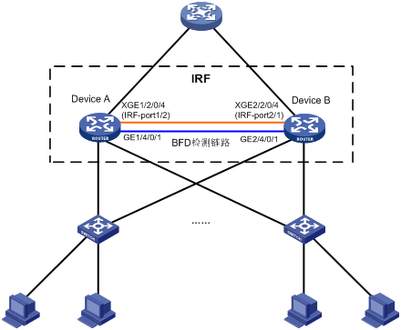
由于网络规模迅速扩大,当前中心设备(Device A)转发能力已经不能满足需求,现需要在保护现有投资的基础上将网络转发能力提高一倍,并要求网络易管理、易维护。
2. 组网图
图3-14 IRF典型配置组网图(BFD MAD检测方式)
3. 配置思路
· Device A处于局域网的汇聚层,为了将汇聚层的转发能力提高一倍,需要另外增加一台设备Device B。
· 鉴于IRF技术具有管理简便、网络扩展能力强、可靠性高等优点,所以本例使用IRF技术构建网络汇聚层(即在Device A和Device B上配置IRF功能),接入层设备通过聚合双链路上行。
· 为了防止万一IRF链路故障导致IRF分裂、网络中存在两个配置冲突的IRF,需要启用MAD检测功能。因为成员设备比较少,我们采用BFD MAD检测方式来监测IRF的状态。
4. 配置步骤
# 设置Device A的成员编号为1,创建IRF端口2,并将它与物理端口Ten-GigabitEthernet2/0/4绑定。
[Sysname] irf member 1
Info: Member ID change will take effect after the member reboots and operates in IRF mode.
[Sysname] irf-port 2
[Sysname-irf-port2] port group interface ten-gigabitethernet 2/0/4
[Sysname-irf-port2] quit
# 将当前配置保存到下次启动配置文件。
<Sysname> save
# 将设备的运行模式切换到IRF模式。
[Sysname] chassis convert mode irf
The device will switch to IRF mode and reboot. You are recommended to save the current running configuration and specify the configuration file for the next startup. Continue? [Y/N]:y
Do you want to convert the content of the next startup configuration file flash:/startup.cfg to make it available in IRF mode? [Y/N]:y
Please wait...
Saving the converted configuration file to the main board succeeded.
Slot 1:
Saving the converted configuration file succeeded.
Now rebooting, please wait...
设备重启后Device A组成了只有一台成员设备的IRF。
# 配置Device B的成员编号为2,创建IRF端口1,并将它与物理端口Ten-GigabitEthernet2/0/4绑定。
[Sysname] irf member 2
Info: Member ID change will take effect after the member reboots and operates in IRF mode.
[Sysname] irf-port 1
[Sysname-irf-port1] port group interface ten-gigabitethernet 2/0/4
[Sysname-irf-port1] quit
# 将当前配置保存到下次启动配置文件。
<Sysname> save
# 将设备的运行模式切换到IRF模式。
[Sysname] chassis convert mode irf
The device will switch to IRF mode and reboot. You are recommended to save the current running configuration and specify the configuration file for the next startup. Continue? [Y/N]:y
Do you want to convert the content of the next startup configuration file flash:/startup.cfg to make it available in IRF mode? [Y/N]:y
Please wait...
Saving the converted configuration file to the main board succeeded.
Slot 1:
Saving the converted configuration file succeeded.
Now rebooting, please wait...
设备B重启后与设备A形成IRF。
# 创建三层聚合接口1。
<Sysname> system-view
[Sysname] interface route-aggregation 1
[Sysname-Route-Aggregation1] quit
#分别将接口GigabitEthernet1/4/0/1与GigabitEthernet2/4/0/1加入到聚合组1中。
[Sysname] interface gigabitethernet 1/4/0/1
[Sysname-GigabitEthernet1/4/0/1] port link-aggregation group 1
[Sysname-GigabitEthernet1/4/0/1] quit
[Sysname] interface gigabitethernet 2/4/0/1
[Sysname-GigabitEthernet2/4/0/1] port link-aggregation group 1
[Sysname-GigabitEthernet2/4/0/1] quit
#配置三层聚合接口1的MAD IP地址。
[Sysname] interface route-aggregation 1
[Sysname-Route-Aggregation1] mad bfd enable
[Sysname-Route-Aggregation1] mad ip address 192.168.2.1 24 member 1
[Sysname-Route-Aggregation1] mad ip address 192.168.2.2 24 member 2
[Sysname-Route-Aggregation1] quit
3.12.3 IRF典型配置举例(ARP MAD检测方式)
1. 组网需求
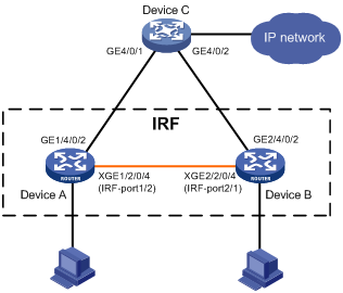
由于网络规模迅速扩大,当前中心设备(Device A)转发能力已经不能满足需求,现需要在保护现有投资的基础上将网络转发能力提高一倍,并要求网络易管理、易维护。
2. 组网图
图3-15 IRF典型配置组网图(ARP MAD检测方式)

3. 配置思路
· 鉴于IRF技术具有管理简便、网络扩展能力强、可靠性高等优点,所以本例使用IRF技术构建网络接入层(即在Device A和Device B上配置IRF功能),IRF通过双链路上行。
· 为了防止万一IRF链路故障导致IRF分裂、网络中存在两个配置冲突的IRF,需要启用MAD检测功能。因为成员设备比较少,我们采用ARP MAD检测方式来监测IRF的状态,复用链路上行传递ARP MAD报文。为防止环路发生,在IRF和Device C上启用生成树功能。
4. 配置步骤
# 设置Device A的成员编号为1,创建IRF端口2,并将它与物理端口Ten-GigabitEthernet2/0/4绑定。
[Sysname] irf member 1
Info: Member ID change will take effect after the member reboots and operates in IRF mode.
[Sysname] irf-port 2
[Sysname-irf-port2] port group interface ten-gigabitethernet 2/0/4
[Sysname-irf-port2] quit
# 将当前配置保存到下次启动配置文件。
<Sysname> save
# 将设备的运行模式切换到IRF模式。
[Sysname] chassis convert mode irf
The device will switch to IRF mode and reboot. You are recommended to save the current running configuration and specify the configuration file for the next startup. Continue? [Y/N]:y
Do you want to convert the content of the next startup configuration file flash:/startup.cfg to make it available in IRF mode? [Y/N]:y
Please wait...
Saving the converted configuration file to the main board succeeded.
Slot 1:
Saving the converted configuration file succeeded.
Now rebooting, please wait...
设备重启后Device A组成了只有一台成员设备的IRF。
# 配置Device B的成员编号为2,创建IRF端口1,并将它与物理端口Ten-GigabitEthernet3/0/1绑定。
[Sysname] irf member 2
Info: Member ID change will take effect after the member reboots and operates in IRF mode.
[Sysname] irf-port 1
[Sysname-irf-port1] port group interface ten-gigabitethernet 2/0/4
[Sysname-irf-port1] quit
# 将当前配置保存到下次启动配置文件。
<Sysname> save
# 将设备的运行模式切换到IRF模式。
[Sysname] chassis convert mode irf
The device will switch to IRF mode and reboot. You are recommended to save the current running configuration and specify the configuration file for the next startup. Continue? [Y/N]:y
Do you want to convert the content of the next startup configuration file flash:/startup.cfg to make it available in IRF mode? [Y/N]:y
Please wait...
Saving the converted configuration file to the main board succeeded.
Slot 1:
Saving the converted configuration file succeeded.
Now rebooting, please wait...
设备B重启后与设备A形成IRF。
(3) 配置ARP MAD检测
# 在IRF上全局使能生成树协议,并配置MST域,以防止环路的发生。
[Sysname] stp global enable
[Sysname] stp region-configuration
[Sysname-mst-region] region-name arpmad
[Sysname-mst-region] instance 1 vlan 3
[Sysname-mst-region] active region-configuration
[Sysname-mst-region] quit
# 将IRF配置为MAC地址立即改变。
[Sysname] undo irf mac-address persistent
# 设置IRF域编号为1。
# 创建VLAN 3,并将Device A(成员编号为1)上的端口1/4/0/2和Device B(成员编号为2)上的端口2/4/0/2加入VLAN中。
[Sysname-vlan3] port gigabitethernet 1/4/0/2 gigabitethernet 2/4/0/2
[Sysname-vlan3] quit
# 创建VLAN-interface3,并在该接口下配置IP地址,使能ARP MAD功能。
[Sysname] interface vlan-interface 3
[Sysname-Vlan-interface3] mad arp enable
You need to assign a domain ID (range: 0-4294967295)
[Current domain is: 1]:
The assigned domain ID is: 1
[Sysname-Vlan-interface3] ip address 192.168.2.1 24
![]()
如果中间设备是一个IRF系统,则必须通过配置确保其IRF域编号与被检测的IRF系统不同。
Device C作为中间设备来转发、处理免费ARP报文,协助Device A和Device B进行多Active检测。从节约成本的角度考虑,使用一台支持ARP功能的设备即可。
# 在全局使能生成树协议,并配置MST域,以防止环路的发生。
[DeviceC] stp global enable
[DeviceC] stp region-configuration
[DeviceC-mst-region] region-name arpmad
[DeviceC-mst-region] instance 1 vlan 3
[DeviceC-mst-region] active region-configuration
[DeviceC-mst-region] quit
# 创建VLAN 3,并将端口GigabitEthernet4/0/1和GigabitEthernet4/0/2加入VLAN 3中,用于转发ARP MAD报文。
[DeviceC-vlan3] port gigabitethernet 4/0/1 gigabitethernet 4/0/2
[DeviceC-vlan3] quit
3.12.4 IRF典型配置举例(ND MAD检测方式)
1. 组网需求
IPv6网络中,由于网络规模迅速扩大,当前中心设备(Device A)转发能力已经不能满足需求,现需要在保护现有投资的基础上将网络转发能力提高一倍,并要求网络易管理、易维护。
2. 组网图
图3-16 IRF典型配置组网图(ND MAD检测方式)
3. 配置思路
· 鉴于IRF技术具有管理简便、网络扩展能力强、可靠性高等优点,所以本例使用IRF技术构建网络接入层(即在Device A和Device B上配置IRF功能),IRF通过双链路上行。
· 为了防止万一IRF链路故障导致IRF分裂、网络中存在两个配置冲突的IRF,需要启用MAD检测功能。因为成员设备比较少,我们采用ND MAD检测方式来监测IRF的状态,复用链路上行传递ND MAD报文。为防止环路发生,在IRF和Device C上启用生成树功能。
4. 配置步骤
# 设置Device A的成员编号为1,创建IRF端口2,并将它与物理端口Ten-GigabitEthernet2/0/4绑定。
[Sysname] irf member 1
Info: Member ID change will take effect after the member reboots and operates in IRF mode.
[Sysname] irf-port 2
[Sysname-irf-port2] port group interface ten-gigabitethernet 2/0/4
[Sysname-irf-port2] quit
# 将当前配置保存到下次启动配置文件。
<Sysname> save
# 将设备的运行模式切换到IRF模式。
[Sysname] chassis convert mode irf
The device will switch to IRF mode and reboot. You are recommended to save the current running configuration and specify the configuration file for the next startup. Continue? [Y/N]:y
Do you want to convert the content of the next startup configuration file flash:/startup.cfg to make it available in IRF mode? [Y/N]:y
Please wait...
Saving the converted configuration file to the main board succeeded.
Slot 1:
Saving the converted configuration file succeeded.
Now rebooting, please wait...
设备重启后Device A组成了只有一台成员设备的IRF。
# 配置Device B的成员编号为2,创建IRF端口1,并将它与物理端口Ten-GigabitEthernet2/0/4绑定。
[Sysname] irf member 2
Info: Member ID change will take effect after the member reboots and operates in IRF mode.
[Sysname] irf-port 1
[Sysname-irf-port1] port group interface ten-gigabitethernet 2/0/4
[Sysname-irf-port1] quit
# 将当前配置保存到下次启动配置文件。
<Sysname> save
# 将设备的运行模式切换到IRF模式。
[Sysname] chassis convert mode irf
The device will switch to IRF mode and reboot. You are recommended to save the current running configuration and specify the configuration file for the next startup. Continue? [Y/N]:y
Do you want to convert the content of the next startup configuration file flash:/startup.cfg to make it available in IRF mode? [Y/N]:y
Please wait...
Saving the converted configuration file to the main board succeeded.
Slot 1:
Saving the converted configuration file succeeded.
Now rebooting, please wait...
设备B重启后与设备A形成IRF。
(3) 配置ND MAD检测
# 在IRF上全局使能生成树协议,并配置MST域,以防止环路的发生。
[Sysname] stp global enable
[Sysname] stp region-configuration
[Sysname-mst-region] region-name arpmad
[Sysname-mst-region] instance 1 vlan 3
[Sysname-mst-region] active region-configuration
[Sysname-mst-region] quit
# 将IRF配置为桥MAC立即改变。
[Sysname] undo irf mac-address persistent
# 设置IRF域编号为1。
# 创建VLAN 3,并将Device A(成员编号为1)上的端口GigabitEthernet1/4/0/2和Device B(成员编号为2)上的端口GigabitEthernet2/4/0/2加入VLAN 3中。
[Sysname-vlan3] port gigabitethernet 1/4/0/2 gigabitethernet 2/4/0/2
[Sysname-vlan3] quit
# 创建VLAN-interface3,并配置IPv6地址,使能ND MAD检测功能。
[Sysname] interface vlan-interface 3
[Sysname-Vlan-interface3] ipv6 address 2001::1 64
[Sysname-Vlan-interface3] mad nd enable
You need to assign a domain ID (range: 0-4294967295)
[Current domain is: 1]:
The assigned domain ID is: 1
![]()
如果中间设备是一个IRF系统,则必须通过配置确保其IRF域编号与被检测的IRF系统不同。
Device C作为中间设备来转发、处理ND报文,协助Device A和Device B进行多Active检测。从节约成本的角度考虑,使用一台支持ND功能的设备即可。
# 在全局使能生成树协议,并配置MST域,以防止环路的发生。
[DeviceC] stp global enable
[DeviceC] stp region-configuration
[DeviceC-mst-region] region-name arpmad
[DeviceC-mst-region] instance 1 vlan 3
[DeviceC-mst-region] active region-configuration
[DeviceC-mst-region] quit
# 创建VLAN 3,并将端口GigabitEthernet4/0/1和GigabitEthernet4/0/2加入VLAN 3中,用于转发ND MAD报文。
[DeviceC-vlan3] port gigabitethernet 4/0/1 gigabitethernet 4/0/2
[DeviceC-vlan3] quit
3.12.5 将成员设备从IRF模式恢复到独立运行模式配置举例
1. 组网需求
如图3-17所示,IRF已经稳定运行,Device A和Device B是IRF的成员设备。现因网络调整,需要将Device A和Device B从IRF模式下恢复到独立运行模式待用。
2. 组网图
图3-17 将成员设备从IRF模式恢复到独立运行模式组网图
3. 配置思路
(1) 断开IRF连接。可以直接将IRF物理连接线缆拔出也可以使用命令行关闭主设备上所有的IRF物理端口。本举例采用命令行关闭的方式。
(2) IRF分裂后,分别将两台成员设备从IRF模式切换到独立运行模式。
4. 配置步骤
MemberID Slot Role Priority CPU-Mac Description
*+1 0 Master 1 00e0-fc0a-15e0 DeviceA
1 1 Standby 1 00e0-fc0f-8c02 DeviceA
2 0 Standby 1 00e0-fc0f-15e1 DeviceB
2 1 Standby 1 00e0-fc0f-15e2 DeviceB
--------------------------------------------------
* indicates the device is the master.
+ indicates the device through which the user logs in.
The Bridge MAC of the IRF is: 000f-e26a-58ed
Auto upgrade : no
Mac persistent : always
Domain ID : 0
(2) 断开IRF连接:手工关闭主设备(Device A)的IRF物理端口Ten-Gigabitethernet 1/2/0/4。(本举例中只有一条IRF物理链路,如果有多条,则需要手工关闭所有的IRF物理端口)
[IRF] interface ten-gigabitethernet 1/2/0/4
[IRF-Ten-Gigabitethernet1/2/0/4] shutdown
[IRF-Ten-Gigabitethernet1/2/0/4] quit
(3) 将Device A的运行模式切换到独立运行模式。
[IRF] undo chassis convert mode
The device will switch to stand-alone mode and reboot. You are recommended to save the current running configuration and specify the configuration file for the next startup. Continue? [Y/N]:y
Do you want to convert the content of the next startup configuration file flash:/vrpcfg.cfg to make it available in stand-alone mode? [Y/N]:y
Please wait.............
Saving the converted configuration file to main board succeeded.
Chassis 1 Slot 1:
Saving the converted configuration file succeeded.
Now rebooting, please wait...
Device A自动重启来完成模式的切换。
(4) 登录Device B后,将Device B的运行模式切换到独立运行模式。
[IRF] undo chassis convert mode
The device will switch to stand-alone mode and reboot. You are recommended to save the current running configuration and specify the configuration file for the next startup. Continue? [Y/N]:y
Do you want to convert the content of the next startup configuration file flash:/vrpcfg.cfg to make it available in stand-alone mode? [Y/N]:y
Please wait.............
Saving the converted configuration file to main board succeeded.
Chassis 2 Slot 1:
Saving the converted configuration file succeeded.
Now rebooting, please wait...
Device B自动重启来完成模式的切换。
![]()
如果IRF上创建了VLAN接口、配置了IP地址,并且Device A和Device B上都存在该VLAN的成员端口(即配置了端口加入VLAN)。此时,Device A和Device B恢复到独立运行模式后,会产生IP地址冲突,请登录其中一台设备,修改该VLAN接口的IP地址。
4 附录
4.1 附录A MSR产品组建IRF时的限制
MSR产品在组建IRF时,对款型、板卡类型、软件特性的限制情况,如表4-1所示。
表4-1 组建IRF时的限制情况
说明 | 类型 | 限制情况 |
支持IRF的款型 | MSR 2630 | 品牌、款型相同时支持组建IRF |
MSR 3600-28/3600-51 | 品牌、款型相同时支持组建IRF | |
MSR 3610/3620/3620-DP/3640/3660 | 品牌、款型相同时支持组建IRF | |
MSR 5620/5660/5680 | 品牌、MPU、SPU相同时支持组建IRF | |
支持的板卡类型 | 所有语音板卡 | 语音板卡只支持单机模式 |
所有WLAN板卡 | WLAN只支持单机模式 | |
FCM板卡 | PCM只支持单机模式 | |
国密卡 | IRF模式下,主从设备必须同时安装国密卡 | |
IRF模式下的软件特性 | 二层转发 | IRF口不支持在主从设备间转发二层流量 |
二层聚合 | 不支持跨框的二层聚合 | |
IPSec、IKE | Ipsec抗重放以及DPD特性要求在同一个成员设备上处理 | |
Session | Session不支持在成员设备间备份,NAT、ASPF、AFT等需要建立会话的业务要求报文来回路径都在同一个成员设备上 | |
拨号 | 不支持AUX、AM、ISDN接口拨号 | |
WEB网管 | IRF模式下不支持WEB网管 | |
内置AC | IRF模式下不支持内置AC | |
配置回滚 | IRF模式下不支持配置回滚 |
- 2022-02-18回答
- 评论(0)
- 举报
-
(0)

两台设备做irf bfd检测,接口按实际接口peizhi
- 2022-02-18回答
- 评论(2)
- 举报
-
(0)
你好!irf网络拓扑误区,那个是核心和汇聚?谢谢
编辑答案


亲~登录后才可以操作哦!
确定你的邮箱还未认证,请认证邮箱或绑定手机后进行当前操作
举报
×
侵犯我的权益
×
侵犯了我企业的权益
×
- 1. 您举报的内容是什么?(请在邮件中列出您举报的内容和链接地址)
- 2. 您是谁?(身份证明材料,可以是身份证或护照等证件)
- 3. 是哪家企业?(营业执照,单位登记证明等证件)
- 4. 您与该企业的关系是?(您是企业法人或被授权人,需提供企业委托授权书)
抄袭了我的内容
×
原文链接或出处
诽谤我
×
- 1. 您举报的内容以及侵犯了您什么权益?(请在邮件中列出您举报的内容、链接地址,并给出简短的说明)
- 2. 您是谁?(身份证明材料,可以是身份证或护照等证件)
对根叔社区有害的内容
×
不规范转载
×
举报说明
是这样的,一般核心区域的话是所有网段的网关所在的设备,而汇聚一般就是起到接入层的接入层上连线汇聚的作用,当然看网络规模,有些网络是接入直接连核心,中间没有汇聚层。或者还有种情况就是超大型园区网络,比如每栋楼都有20个网段,那么可能20个网段的地址网关配置在汇聚上,所有接入连接汇聚,然后每栋楼的汇聚再连接核心,因为每栋楼都需要互访,那么就需要通过核心设备来打通各个楼栋的路由