irf三台或者四台交换机,环式堆叠有案例吗
- 0关注
- 0收藏,2099浏览


您好,请知:
以下是配置举例:
5 四台成员设备的IRF配置举例
5.1 组网需求
· 如图2所示,由于网络规模迅速扩大,汇聚层SW设备扩展至N台,当前中心设备设备A的转发能力已经不能满足需求。现在需要另增三台设备,组成一个四框IRF才能满足当前网络的转发需求。
· 升级到四框IRF设备后,必须保证即使IRF中有N台设备发生故障(1≤N≤3),RouterA与汇聚层交换机(如:SW1,SW2等)之间通信也不能中断。
图2 四台成员设备的IRF典型配置组网图(采用LACP MAD)
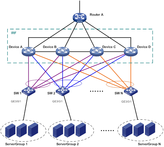
表2 IP地址配置信息
设备 | 接口 | IP地址 |
RouterA | Vlan-interface41 | 172.24.41.2/24 |
Vlan-interface50 | 172.24.1.2/24 | |
IRF | Vlan-interface41 | 172.24.41.254/24 |
Vlan-interface10 | 172.24.10.254/24 | |
Vlan-interface20 | 172.24.20.254/24 | |
… | … | |
Vlan-interfaceN | 172.24.N.254/24 |
表3 IRF设备互联信息
设备 | IRF端口 | 对端IRF端口 | IRF成员端口 |
Device A | irf-port 1/1 | irf-port 4/2 | XGE1/2/0/4 |
Device A | irf-port 1/2 | irf-port 2/1 | XGE1/2/0/1 |
Device B | irf-port 2/1 | irf-port 1/2 | XGE2/4/0/2 |
Device B | irf-port 2/2 | irf-port 3/1 | XGE2/3/0/30 |
Device C | irf-port 3/1 | irf-port 2/2 | XGE3/3/0/15 |
Device C | irf-port 3/2 | irf-port 4/1 | XGE3/12/0/1 |
Device D | irf-port 4/1 | irf-port 3/2 | XGE4/6/0/4 |
Device D | irf-port 4/2 | irf-port 1/1 | XGE4/6/0/2 |
表4 IRF设备的上下行互联信息
IRF的对端设备 | 接口 | 所属vlan | 所属聚合组 |
下行连SW2 | XGE1/3/0/1 | Vlan 13(BFD MAD) |
|
下行连SW2 | XGE2/3/0/1 | Vlan 13(BFD MAD) |
|
下行连SW2 | XGE3/3/0/1 | Vlan 13(BFD MAD) |
|
下行连SW2 | XGE4/3/0/1 | Vlan 13(BFD MAD) |
|
下行连SW1 | XGE1/3/0/3 | Vlan 10 | Bridge-aggregation 1(LACP MAD) |
下行连SW1 | XGE2/3/0/3 | Vlan 10 | Bridge-aggregation 1(LACP MAD) |
下行连SW1 | XGE3/3/0/3 | Vlan 10 | Bridge-aggregation 1(LACP MAD) |
下行连SW1 | XGE4/3/0/3 | Vlan 10 | Bridge-aggregation 1(LACP MAD) |
下行连SW2 | XGE1/3/0/4 | Vlan 20 | Bridge-aggregation 2 |
下行连SW2 | XGE2/3/0/4 | Vlan 20 | Bridge-aggregation 2 |
下行连SW2 | XGE3/3/0/4 | Vlan 20 | Bridge-aggregation 2 |
下行连SW2 | XGE4/3/0/4 | Vlan 20 | Bridge-aggregation 2 |
上行连Router A | XGE1/3/0/8 | Vlan 41 | Bridge-aggregation 1024 |
上行连Router A | XGE2/3/0/8 | Vlan 41 | Bridge-aggregation 1024 |
上行连Router A | XGE3/3/0/8 | Vlan 41 | Bridge-aggregation 1024 |
上行连Router A | XGE4/3/0/8 | Vlan 41 | Bridge-aggregation 1024 |
表5 SW1设备的上下行互联信息
SW1的对端设备 | 接口 | 所属vlan | 所属聚合组 |
下行连服务组 | GE3/0/1 | Vlan 10 |
|
上行连IRF | XGE2/0/21 | Vlan 10 | Bridge-aggregation 1(LACP MAD) |
上行连IRF | XGE2/0/22 | Vlan 10 | Bridge-aggregation 1(LACP MAD) |
上行连IRF | XGE2/0/23 | Vlan 10 | Bridge-aggregation 1(LACP MAD) |
上行连IRF | XGE2/0/24 | Vlan 10 | Bridge-aggregation 1(LACP MAD) |
表6 SW2设备的上下行互联信息
SW2的对端设备 | 接口 | 所属vlan | 所属聚合组 |
下行连服务组 | GE3/0/1 | Vlan 20 |
|
上行连IRF | XGE2/0/21 | Vlan 20 | Bridge-aggregation 1 |
上行连IRF | XGE2/0/22 | Vlan 20 | Bridge-aggregation 1 |
上行连IRF | XGE2/0/23 | Vlan 20 | Bridge-aggregation 1 |
上行连IRF | XGE2/0/24 | Vlan 20 | Bridge-aggregation 1 |
表7 Router A设备的上下行互联信息
Router A的对端设备 | 接口 | 所属vlan | 所属聚合组 |
下行连IRF | XGE2/0/1 | Vlan 41 | Bridge-aggregation 1 |
下行连IRF | XGE2/0/2 | Vlan 41 | Bridge-aggregation 1 |
下行连IRF | XGE2/0/3 | Vlan 41 | Bridge-aggregation 1 |
下行连IRF | XGE2/0/4 | Vlan 41 | Bridge-aggregation 1 |
上行连外网 | XGE2/0/2 | Vlan 50 |
|
5.2 配置思路
· 为避免成员设备的单点故障影响到正常的业务转发,可在IRF中配置跨框聚合端口进行业务转发。
· LACP MAD检测只需在一个聚合组中配置即可,其他聚合组中无需配置。LACP MAD检测使用的二层交换机必须为H3C的交换机设备且使用的软件版本必须能够识别、处理携带了ActiveID值的LACPDU协议报文,在本例中使用SW 1作为LACP MAD检测的中间设备。
5.3 配置步骤
5.3.1 搭建IRF
1. Device A的配置
(1) 设置Device A的成员编号为1
<DeviceA> system-view
[DeviceA] irf member 1
(2) 配置IRF端口1与物理端口Ten-GigabitEthernet 2/0/4绑定
[DeviceA] irf-port 1
[DeviceA-irf-port1] port group interface ten-gigabitethernet 2/0/4
[DeviceA-irf-port1] quit
(3) 配置IRF端口2与物理端口Ten-GigabitEthernet 2/0/1绑定
[DeviceA] irf-port 2
[DeviceA-irf-port2] port group interface ten-gigabitethernet 2/0/1
[DeviceA-irf-port2] quit
(4) 将当前配置保存到下次启动配置文件
[DeviceA] save
The current configuration will be written to the device. Are you sure? [Y/N]:y
Please input the file name(*.cfg)[cfa0:/irf.cfg]
(To leave the existing filename unchanged, press the enter key):
cfa0:/irf.cfg exists, overwrite? [Y/N]:y
Validating file. Please wait.....................................
Saved the current configuration to mainboard device successfully.
(5) 将Device A的运行模式切换到IRF模式之后,设备会自动重启
[DeviceA] chassis convert mode irf
The device will switch to IRF mode and reboot.
You are recommended to save the current running configuration and specify the c
onfiguration file for the next startup. Continue? [Y/N]:y
Do you want to convert the content of the next startup configuration file flash
:/startup.cfg to make it available in stack mode? [Y/N]:y
2. Device B的配置
(1) 设置Device B的成员编号为2
<DeviceB> system-view
[DeviceB] irf member 2
(2) 配置IRF端口1与物理端口Ten-GigabitEthernet 4/0/2绑定
[DeviceB] irf-port 1
[DeviceB-irf-port1] port group interface ten-gigabitethernet 4/0/2
[DeviceB-irf-port1] quit
(3) 配置IRF端口2与物理端口Ten-GigabitEthernet 3/0/30绑定
[DeviceB] irf-port 2
[DeviceB-irf-port2] port group interface ten-gigabitethernet3/0/30
[DeviceB-irf-port2] quit
(4) 保存配置
[DeviceB] save
The current configuration will be written to the device. Are you sure? [Y/N]:y
Please input the file name(*.cfg)[cfa0:/irf.cfg]
(To leave the existing filename unchanged, press the enter key):
cfa0:/irf.cfg exists, overwrite? [Y/N]:y
Validating file. Please wait.....................................
Saved the current configuration to mainboard device successfully.
(5) 参照图2和端口连接表连接Device A和Device B之间的IRF端口
(6) 将设备的运行模式切换到IRF模式
[DeviceB] chassis convert mode irf
The device will switch to IRF mode and reboot.
You are recommended to save the current running configuration and specify the c
onfiguration file for the next startup. Continue? [Y/N]:y
Do you want to convert the content of the next startup configuration file flash
:/startup.cfg to make it available in stack mode? [Y/N]:y
Now rebooting, please wait...
3. Device C的配置
(1) 设置Device C的成员编号为3
<DeviceC> system-view
[DeviceC] irf member 3
(2) 配置IRF端口1与物理端口Ten-GigabitEthernet 3/0/15绑定
[DeviceC] irf-port 1
[DeviceC-irf-port1] port group interface ten-gigabitethernet 3/0/15
[DeviceC-irf-port1] quit
(3) 配置IRF端口2与物理端口Ten-GigabitEthernet 12/0/1绑定
[DeviceC] irf-port 2
[DeviceC-irf-port2] port group interface ten-gigabitethernet12/0/1
[DeviceC-irf-port2] quit
(4) 保存配置
[DeviceC] save
The current configuration will be written to the device. Are you sure? [Y/N]:y
Please input the file name(*.cfg)[cfa0:/irf.cfg]
(To leave the existing filename unchanged, press the enter key):
cfa0:/irf.cfg exists, overwrite? [Y/N]:y
Validating file. Please wait.....................................
Saved the current configuration to mainboard device successfully.
(5) 参照图2和端口连接表连接Device B和Device C之间的IRF端口
(6) 将设备的运行模式切换到IRF模式
[DeviceC] chassis convert mode irf
The device will switch to IRF mode and reboot.
You are recommended to save the current running configuration and specify the c
onfiguration file for the next startup. Continue? [Y/N]:y
Do you want to convert the content of the next startup configuration file flash
:/startup.cfg to make it available in stack mode? [Y/N]:y
Now rebooting, please wait...
4. Device D的配置
(1) 设置Device D的成员编号为4
<DeviceD> system-view
[DeviceD] irf member 4
(2) 配置IRF端口1与物理端口Ten-GigabitEthernet 6/0/4绑定
[DeviceD] irf-port 1
[DeviceD-irf-port1] port group interface ten-gigabitethernet 6/0/4
[DeviceD-irf-port1] quit
(3) 配置IRF端口2与物理端口Ten-GigabitEthernet 6/0/2绑定
[DeviceD] irf-port 2
[DeviceD-irf-port2] port group interface ten-gigabitethernet6/0/2
[DeviceD-irf-port2] quit
(4) 保存配置
[DeviceD] save
The current configuration will be written to the device. Are you sure? [Y/N]:y
Please input the file name(*.cfg)[cfa0:/irf.cfg]
(To leave the existing filename unchanged, press the enter key):
cfa0:/irf.cfg exists, overwrite? [Y/N]:y
Validating file. Please wait.....................................
Saved the current configuration to mainboard device successfully.
(5) 参照图2和端口连接表连接Device C和Device D以及Device A和Device D之间的IRF端口
(6) 将设备的运行模式切换到IRF模式
[DeviceD] chassis convert mode irf
The device will switch to IRF mode and reboot.
You are recommended to save the current running configuration and specify the c
onfiguration file for the next startup. Continue? [Y/N]:y
Do you want to convert the content of the next startup configuration file flash
:/startup.cfg to make it available in stack mode? [Y/N]:y
Now rebooting, please wait...
5.3.2 LACP MAD配置
在前面配置完成并重新启动后,IRF已经组建完成,此时可以进行各个业务模块的配置。IRF形成之后,可以从任何一台成员设备登录进行配置,设备名称缺省为Master的名称(此例中为Device A)。
# 创建连接接入层交换机SW 1的动态聚合组,编号为1,并使能LACP MAD检测功能。
<DeviceA> system-view
[DeviceA] interface bridge-aggregation 1
[DeviceA-Bridge-Aggregation1] link-aggregation mode dynamic
[DeviceA-Bridge-Aggregation1] mad enable
You need to assign a domain ID (range: 0-4294967295)
[Current domain is: 0]:
The assigned domain ID is: 0
MAD LACP only enable on dynamic aggregation interface.
[DeviceA-Bridge-Aggregation1] quit
# 使用接口批量配置功能配置连接SW 1的端口加入聚合组1。
[DeviceA] interface range ten-gigabitethernet 1/3/0/3 ten-gigabitethernet 2/3/0/3 ten-gigabitethernet 3/3/0/3 ten-gigabitethernet 4/3/0/3
[DeviceA-if-range] port link-aggregation group 1
[DeviceA-if-range] quit
5.3.3 IRF下行业务配置
1. IRF的配置
# 创建连接接入层交换机SW 2的聚合组,编号为2。
[DeviceA] interface bridge-aggregation 2
[DeviceA-Bridge-Aggregation2] quit
# 使用接口批量配置功能配置连接SW 2的端口加入聚合组2。
[DeviceA] interface ten-gigabitethernet 1/3/0/4 ten-gigabitethernet 2/3/0/4 ten-gigabitethernet 3/3/0/4 ten-gigabitethernet 4/3/0/4
[DeviceA-if-range] port link-aggregation group 2
[DeviceA-if-range] quit
# 配置与SW 1之间通过Vlan-interface 10连接。
[DeviceA] vlan 10
[DeviceA-vlan10] quit
[DeviceA] interface vlan-interface 10
[DeviceA-Vlan-interface10] ip address 172.24.10.254 24
[DeviceA-Vlan-interface10] quit
[DeviceA] interface bridge-aggregation 1
[DeviceA-Bridge-Aggregation1] port link-type trunk
[DeviceA-Bridge-Aggregation1] undo port trunk permit vlan 1
[DeviceA-Bridge-Aggregation1] port trunk permit vlan 10
[DeviceA-Bridge-Aggregation1] quit
# 配置与SW 2之间通过Vlan-interface 20连接。
[DeviceA] vlan 20
[DeviceA-vlan20] quit
[DeviceA] interface vlan-interface 20
[DeviceA-Vlan-interface20] ip address 172.24.20.254 24
[DeviceA-Vlan-interface20] quit
[DeviceA] interface bridge-aggregation 2
[DeviceA-Bridge-Aggregation2] port link-type trunk
[DeviceA-Bridge-Aggregation2] undo port trunk permit vlan 1
[DeviceA-Bridge-Aggregation2] port trunk permit vlan 20
[DeviceA-Bridge-Aggregation2] quit
2. SW 1的配置
# 创建连接IRF的动态聚合组,编号为1,该聚合组同时用于IRF的LACP MAD检测。
<SW1> system-view
[SW1] interface bridge-aggregation 1
[SW1-Bridge-Aggregation1] link-aggregation mode dynamic
[SW1-Bridge-Aggregation1] quit
# 使用接口批量配置功能配置连接IRF的端口加入聚合组1。
[SW1] interface range ten-gigabitethernet 2/0/21 to ten-gigabitethernet 2/0/24
[SW1-if-range] port link-aggregation group 1
[SW1-if-range] quit
# 接入设备SW1上创建所有VLAN。
[SW1] vlan all
# 配置与IRF连接的端口。
[SW1] interface bridge-aggregation 1
[SW1-Bridge-Aggregation1] port link-type trunk
[SW1-Bridge-Aggregation1] undo port trunk permit vlan 1
[SW1-Bridge-Aggregation1] port trunk permit vlan 10
[SW1-Bridge-Aggregation1] quit
# 配置连接服务器的端口GigabitEthernet3/0/1。
[SW1] interface gigabitethernet 3/0/1
[SW1-GigabitEthernet3/0/1] port link-type trunk
[SW1-GigabitEthernet3/0/1] port trunk permit vlan all
[SW1-GigabitEthernet3/0/1] undo port trunk permit vlan 1
[SW1-GigabitEthernet3/0/1] quit
3. SW 2的配置
# 创建连接IRF的聚合组,编号为1。
<SW2> system-view
[SW2] interface bridge-aggregation 1
[SW2-Bridge-Aggregation1] quit
# 使用接口批量配置功能配置连接IRF的端口加入聚合组1。
[SW2] interface range ten-gigabitethernet 2/0/21 to ten-gigabitethernet 2/0/24
[SW2-if-range] port link-aggregation group 1
[SW2-if-range] quit
# 接入设备SW 2上创建所有VLAN。
[SW2] vlan all
# 配置与IRF连接的端口。
[SW2] interface bridge-aggregation 1
[SW2-Bridge-Aggregation1] port link-type trunk
[SW2-Bridge-Aggregation1] undo port trunk permit vlan 1
[SW2-Bridge-Aggregation1] port trunk permit vlan 20
[SW2-Bridge-Aggregation1] quit
# 配置连接服务器的端口。
[SW2] interface gigabitethernet 3/0/1
[SW2-GigabitEthernet3/0/1] port link-type trunk
[SW2-GigabitEthernet3/0/1] port trunk permit vlan all
[SW2-GigabitEthernet3/0/1] undo port trunk permit vlan 1
[SW2-GigabitEthernet3/0/1] quit
5.3.4 IRF上行业务配置
1. IRF的配置
# 创建连接出口路由器Router A的聚合组,编号为1024。
[DeviceA] interface bridge-aggregation 1024
[DeviceA-Bridge-Aggregation1024] quit
# 使用接口批量配置功能配置连接Router A的端口加入聚合组1024。
[DeviceA] interface range ten-gigabitethernet 1/3/0/8 ten-gigabitethernet 2/3/0/8 ten-gigabitethernet 3/3/0/8 ten-gigabitethernet 4/3/0/8
[DeviceA-if-range] port link-aggregation group 1024
[DeviceA-if-range] quit
# 配置与Router A之间通过Vlan-interface41连接。
[DeviceA] vlan 41
[DeviceA-vlan41] quit
[DeviceA] interface vlan-interface 41
[DeviceA-Vlan-interface41] ip address 172.24.41.254 24
[DeviceA-Vlan-interface41] quit
[DeviceA] interface bridge-aggregation 1024
[DeviceA-Bridge-Aggregation1024] port access vlan 41
[DeviceA-Bridge-Aggregation1024] quit
# 配置IRF与出口路由器之间运行OSPF路由协议。
[DeviceA] interface loopback 0
[DeviceA-LoopBack0] ip address 172.24.254.1 255.255.255.255
[DeviceA-LoopBack0] quit
[DeviceA] ospf 1 router-id 172.24.254.1
[DeviceA-ospf-1] import-route direct
[DeviceA-ospf-1] area 0
[DeviceA-ospf-1-area-0.0.0.0] network 172.24.41.0 0.0.0.255
[DeviceA-ospf-1-area-0.0.0.0] quit
[DeviceA-ospf-1] quit
2. Router A的配置
出口路由器配置本用例只描述与IRF连接的部分,外网使用何种路由协议不予描述。
# 创建连接IRF的聚合组,编号为1。
<RouterA> system-view
[RouterA] interface bridge-aggregation 1
[RouterA-Bridge-Aggregation1] quit
# 配置连接IRF的端口加入聚合组1。
[RouterA] interface range ten-gigabitethernet 2/0/1 to interface ten-gigabitethernet 2/0/4
[RouterA-if-range] port link-aggregation group 1
[RouterA-if-range] quit
# 配置与IRF之间通过Vlan-interface 41连接。
[RouterA] vlan 41
[RouterA-vlan41] quit
[RouterA] interface vlan-interface 41
[RouterA-Vlan-interface41] ip address 172.24.41.2 24
[RouterA-Vlan-interface41] quit
[RouterA] interface bridge-aggregation 1
[RouterA-Bridge-Aggregation1] port access vlan 41
[RouterA-Bridge-Aggregation1] quit
# 配置Router A通过Vlan-interface 50连接外网。
[RouterA] vlan 50
[RouterA-vlan50] quit
[RouterA] interface vlan-interface 50
[RouterA-Vlan-interface50] ip address 172.24.1.2 24
[RouterA-Vlan-interface50] quit
[RouterA] interface ten-gigabitethernet 4/0/3
[RouterA-Ten-GigabitEthernet4/0/3] port link-mode bridge
[RouterA-Ten-GigabitEthernet4/0/3] port access vlan 50
[RouterA-Ten-GigabitEthernet4/0/3] quit
# 配置Router A与IRF之间运行OSPF路由协议。
[RouterA] interface loopback 0
[RouterA-LoopBack0] ip addresss 172.24.254.2 255.255.255.255
[RouterA-LoopBack0] quit
[RouterA] ospf 1 router-id 172.24.254.2
[RouterA-ospf-1] import-route direct
[RouterA-ospf-1] area 0
[RouterA-ospf-1-area-0.0.0.0] network 172.24.41.0 0.0.0.255
[RouterA-ospf-1-area-0.0.0.0] quit
[RouterA-ospf-1] quit
5.4 验证配置
(1) 验证IRF是否建立成功
# 使用display irf topology命令查看八个IRF口都是UP状态,说明四台设备建立IRF成功。
<DeviceA> display irf topology
Topology Info
-------------------------------------------------------------------------
IRF-Port1 IRF-Port2
Switch Link neighbor Link neighbor Belong To
1 UP 4 UP 2 0210-fc01-0000
4 UP 3 UP 1 0210-fc01-0000
3 UP 2 UP 4 0210-fc01-0000
2 UP 1 UP 3 0210-fc01-0000
(2) 验证跨框聚合链路备份功能
# 从serverGroup 1任意挑选一台PC ping外网IP,同时关闭IRF的上行端口Ten-GigabitEthernet 1/3/0/8。
[DeviceA] interface ten-gigabitethernet 1/3/0/8
[DeviceA-Ten-GigabitEthernet1/3/0/8] shutdown
仍然可以ping通外网。
# 重新开启IRF的上行端口Ten-GigabitEthernet 1/3/0/8端口,持续ping外网IP。
[DeviceA-Ten-GigabitEthernet1/3/0/8] undo shutdown
[DeviceA-Ten-GigabitEthernet1/3/0/8] quit
# 关闭IRF的另一个上行端口Ten-GigabitEthernet 2/3/0/8。
[DeviceA] interface ten-gigabitethernet 2/3/0/8
[DeviceA-Ten-GigabitEthernet2/3/0/8] shutdown
仍然可以ping通外网。
- 2022-10-28回答
- 评论(0)
- 举报
-
(0)
暂无评论
编辑答案


亲~登录后才可以操作哦!
确定你的邮箱还未认证,请认证邮箱或绑定手机后进行当前操作
举报
×
侵犯我的权益
×
侵犯了我企业的权益
×
- 1. 您举报的内容是什么?(请在邮件中列出您举报的内容和链接地址)
- 2. 您是谁?(身份证明材料,可以是身份证或护照等证件)
- 3. 是哪家企业?(营业执照,单位登记证明等证件)
- 4. 您与该企业的关系是?(您是企业法人或被授权人,需提供企业委托授权书)
抄袭了我的内容
×
原文链接或出处
诽谤我
×
- 1. 您举报的内容以及侵犯了您什么权益?(请在邮件中列出您举报的内容、链接地址,并给出简短的说明)
- 2. 您是谁?(身份证明材料,可以是身份证或护照等证件)
对根叔社区有害的内容
×
不规范转载
×
举报说明
暂无评论