irf堆叠
- 1关注
- 0收藏,1732浏览


最佳答案


您好,请知:
以下是IRF的配置案例,请参考:
4 两台成员设备的IRF配置举例
4.1 组网需求
· 如图1所示,Device A为公司的核心设备,但由于公司网络规模日益增大,汇聚层SW设备扩展至N台,Device A单台设备的转发能力已无法达到公司网络的需求。为了拓展核心设备的转发能力,又尽量不改变现有网络。现公司希望增加Device B,与Device A组成IRF,来满足当前网络的需求。
· IRF的上行设备(Router A和Router B)为公司网络的出口路由器;IRF的下行交换机(SW 1、SW 2等)为各个服务器集群的汇聚层设备。
图1 IRF典型配置组网图
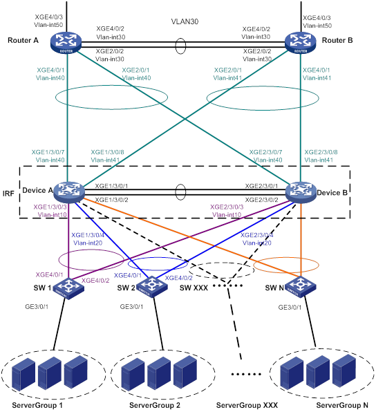
设备 | 接口 | IP地址 | 设备 | 接口 | IP地址 |
Router A | Vlan-int30 | 172.24.2.2/24 | Router B | Vlan-int30 | 172.24.2.3/24 |
| Vlan-int40 | 172.24.40.2/24 |
| Vlan-int41 | 172.24.41.3/24 |
| Vlan-int50 | 172.24.1.2/24 |
| Vlan-int50 | 172.24.4.3/24 |
IRF | Vlan-int10 | 172.24.10.254/24 |
|
|
|
| Vlan-int20 | 172.24.20.254/24 |
|
|
|
| Vlan-int40 | 172.24.40.254/24 |
|
|
|
| Vlan-int41 | 172.24.41.254/24 |
|
|
|
4.2 配置思路
· 为避免成员设备的单点故障影响到正常的业务转发,可在IRF中配置跨框聚合端口进行业务转发。
· 为尽量降低IRF分裂对业务造成的影响,可在IRF中配置LACP MAD检测。LACP MAD检测只需在一个聚合组中配置即可,其他聚合组中无需配置。LACP MAD检测使用的中间设备必须为H3C的交换机设备且使用的软件版本必须能够识别、处理携带了ActiveID值的LACPDU协议报文,在本例中使用SW 1作为LACP MAD检测的中间设备。
4.3 配置步骤
4.3.1 搭建IRF
1. Device A的配置
(1) 设置Device A的成员编号为1
<DeviceA> system-view
[DeviceA] irf member 1
(2) 创建IRF端口2,并将它与物理端口Ten-GigabitEthernet 3/0/1和Ten-GigabitEthernet 3/0/2绑定
[DeviceA] irf-port 2
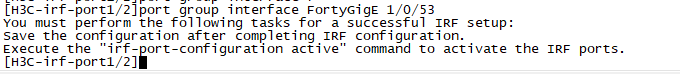
[DeviceA-irf-port2] port group interface ten-gigabitethernet 3/0/1
[DeviceA-irf-port2] port group interface ten-gigabitethernet 3/0/2
[DeviceA-irf-port2] quit
(3) 将当前配置保存到下次启动配置文件
切换运行模式后,设备会自动重启,使新的运行模式生效。为防止配置丢失,请在切换模式前,保存当前配置。
[DeviceA] save
(4) 将Device A的运行模式切换到IRF模式,之后设备会自动重启
[DeviceA] chassis convert mode irf
The device will switch to IRF mode and reboot.
You are recommended to save the current running configuration and specify the co
nfiguration file for the next startup. Continue? [Y/N]:y
Do you want to convert the content of the next startup configuration file cfa0:/
irf.cfg to make it available in stack mode? [Y/N]:y
Now rebooting, please wait...
2. Device B的配置
(1) 设置Device B的成员编号为2
<DeviceB> system-view
[DeviceB] irf member 2
(2) 创建设备的IRF端口1,并将它与物理端口Ten-GigabitEthernet 3/0/1和Ten-GigabitEthernet 3/0/2绑定
[DeviceB] irf-port 1
[DeviceB-irf-port1] port group interface ten-gigabitethernet 3/0/1
[DeviceB-irf-port1] port group interface ten-gigabitethernet 3/0/2
[DeviceB-irf-port1] quit
(3) 保存配置
[DeviceB] save
(4) 参照图1和端口连接表连接Device A和Device B之间的IRF端口
(5) 将设备的运行模式切换到IRF模式
[DeviceB] chassis convert mode irf
The device will switch to IRF mode and reboot.
You are recommended to save the current running configuration and specify the co
nfiguration file for the next startup. Continue? [Y/N]:y
Do you want to convert the content of the next startup configuration file cfa0:
/irf.cfg to make it available in stack mode? [Y/N]:y
Now rebooting, please wait...
4.3.2 LACP MAD配置
在前面配置完成并重新启动后,IRF已经组建完成,此时可以进行各个业务模块的配置。IRF形成之后,可以从任何一台成员设备登录进行配置,设备名称缺省为Master的名称(此例中为Device A)。
# 创建连接接入层交换机SW 1的动态聚合组,编号为1,并使能LACP MAD检测功能。
<DeviceA> system-view
[DeviceA] interface bridge-aggregation 1
[DeviceA-Bridge-Aggregation1] link-aggregation mode dynamic
[DeviceA-Bridge-Aggregation1] mad enable
You need to assign a domain ID (range: 0-4294967295)
[Current domain is: 0]:
The assigned domain ID is: 0
MAD LACP only enable on dynamic aggregation interface.
[DeviceA-Bridge-Aggregation1] quit
# 配置连接SW 1的端口加入聚合组1。
[DeviceA] interface ten-gigabitethernet 1/3/0/3
[DeviceA-Ten-GigabitEthernet1/3/0/3] port link-aggregation group 1
[DeviceA-Ten-GigabitEthernet1/3/0/3] quit
[DeviceA] interface ten-gigabitethernet 2/3/0/3
[DeviceA-Ten-GigabitEthernet2/3/0/3] port link-aggregation group 1
[DeviceA-Ten-GigabitEthernet2/3/0/3] quit
4.3.3 IRF下行业务配置
1. IRF的配置
# 创建连接接入层交换机SW 2的聚合组,编号为2。
[DeviceA] interface bridge-aggregation 2
[DeviceA-Bridge-Aggregation2] quit
# 配置连接SW 2的端口加入聚合组2。
[DeviceA] interface ten-gigabitethernet 1/3/0/4
[DeviceA-Ten-GigabitEthernet1/3/0/4] port link-aggregation group 2
[DeviceA-Ten-GigabitEthernet1/3/0/4] quit
[DeviceA] interface ten-gigabitethernet 2/3/0/4
[DeviceA-Ten-GigabitEthernet2/3/0/4] port link-aggregation group 2
[DeviceA-Ten-GigabitEthernet2/3/0/4] quit
# 配置与SW 1之间通过Vlan-interface 10连接。
[DeviceA] vlan 10
[DeviceA-vlan10] quit
[DeviceA] interface vlan-interface 10
[DeviceA-Vlan-interface10] ip address 172.24.10.254 24
[DeviceA-Vlan-interface10] quit
[DeviceA] interface bridge-aggregation 1
[DeviceA-Bridge-Aggregation1] port link-type trunk
[DeviceA-Bridge-Aggregation1] undo port trunk permit vlan 1
[DeviceA-Bridge-Aggregation1] port trunk permit vlan 10
[DeviceA-Bridge-Aggregation1] quit
# 配置与SW 2之间通过Vlan-interface 20连接。
[DeviceA] vlan 20
[DeviceA-vlan20] quit
[DeviceA] interface vlan-interface 20
[DeviceA-Vlan-interface20] ip address 172.24.20.254 24
[DeviceA-Vlan-interface20] quit
[DeviceA] interface bridge-aggregation 2
[DeviceA-Bridge-Aggregation2] port link-type trunk
[DeviceA-Bridge-Aggregation2] undo port trunk permit vlan 1
[DeviceA-Bridge-Aggregation2] port trunk permit vlan 20
[DeviceA-Bridge-Aggregation2] quit
2. SW 1的配置
# 创建连接IRF的动态聚合组,编号为1,该聚合组同时用于IRF的LACP MAD检测。
<SW1> system-view
[SW1] interface bridge-aggregation 1
[SW1-Bridge-Aggregation1] link-aggregation mode dynamic
[SW1-Bridge-Aggregation1] quit
# 配置连接IRF的端口加入聚合组1。
[SW1] interface ten-gigabitethernet 4/0/1
[SW1-Ten-GigabitEthernet4/0/1] port link-aggregation group 1
[SW1-Ten-GigabitEthernet4/0/1] quit
[SW1] interface ten-gigabitethernet 4/0/2
[SW1-Ten-GigabitEthernet4/0/2] port link-aggregation group 1
[SW1-Ten-GigabitEthernet4/0/2] quit
# 接入设备SW1上创建所有VLAN。
[SW1] vlan all
# 配置与IRF连接的端口。
[SW1] interface bridge-aggregation 1
[SW1-Bridge-Aggregation1] port link-type trunk
[SW1-Bridge-Aggregation1] undo port trunk permit vlan 1
[SW1-Bridge-Aggregation1] port trunk permit vlan 10
[SW1-Bridge-Aggregation1] quit
# 配置连接服务器的端口GigabitEthernet3/0/1。
[SW1] interface gigabitethernet 3/0/1
[SW1-GigabitEthernet3/0/1] port link-type trunk
[SW1-GigabitEthernet3/0/1] port trunk permit vlan all
[SW1-GigabitEthernet3/0/1] undo port trunk permit vlan 1
[SW1-GigabitEthernet3/0/1] quit
3. SW 2的配置
# 创建连接IRF的聚合组,编号为1。
<SW2> system-view
[SW2] interface bridge-aggregation 1
[SW2-Bridge-Aggregation1] quit
# 配置连接IRF的端口加入聚合组1。
[SW2] interface ten-gigabitethernet 4/0/1
[SW2-Ten-GigabitEthernet4/0/1] port link-aggregation group 1
[SW2-Ten-GigabitEthernet4/0/1] quit
[SW2] interface ten-gigabitethernet 4/0/2
[SW2-Ten-GigabitEthernet4/0/2] port link-aggregation group 1
[SW2-Ten-GigabitEthernet4/0/2] quit
# 接入设备SW 2上创建所有VLAN。
[SW2] vlan all
# 配置与IRF连接的端口。
[SW2] interface bridge-aggregation 1
[SW2-Bridge-Aggregation1] port link-type trunk
[SW2-Bridge-Aggregation1] undo port trunk permit vlan 1
[SW2-Bridge-Aggregation1] port trunk permit vlan 20
[SW2-Bridge-Aggregation1] quit
# 配置连接服务器的端口。
[SW2] interface gigabitethernet 3/0/1
[SW2-GigabitEthernet3/0/1] port link-type trunk
[SW2-GigabitEthernet3/0/1] port trunk permit vlan all
[SW2-GigabitEthernet3/0/1] undo port trunk permit vlan 1
[SW2-GigabitEthernet3/0/1] quit
4.3.4 IRF上行业务配置
1. IRF的配置
# 创建连接出口路由器Router A的聚合组,编号为1023。
[DeviceA] interface bridge-aggregation 1023
[DeviceA-Bridge-Aggregation1023] quit
# 配置连接Router A的端口加入聚合组1023。
[DeviceA] interface ten-gigabitethernet 1/3/0/7
[DeviceA-Ten-GigabitEthernet1/3/0/7] port link-aggregation group 1023
[DeviceA-Ten-GigabitEthernet1/3/0/7] quit
[DeviceA] interface ten-gigabitethernet 2/3/0/7
[DeviceA-Ten-GigabitEthernet2/3/0/7] port link-aggregation group 1023
[DeviceA-Ten-GigabitEthernet2/3/0/7] quit
# 配置与Router A之间通过Vlan-interface40连接。
[DeviceA] vlan 40
[DeviceA-vlan40] quit
[DeviceA] interface vlan-interface 40
[DeviceA-Vlan-interface40] ip address 172.24.40.254 24
[DeviceA-Vlan-interface40] quit
[DeviceA] interface bridge-aggregation 1023
[DeviceA-Bridge-Aggregation1023] port access vlan 40
[DeviceA-Bridge-Aggregation1023] quit
# 创建连接出口路由器Router B的聚合组,编号为1024。
[DeviceA] interface bridge-aggregation 1024
[DeviceA-Bridge-Aggregation1024] quit
# 配置连接Router B的端口加入聚合组1024。
[DeviceA] interface ten-gigabitethernet 1/3/0/8
[DeviceA-Ten-GigabitEthernet1/3/0/8] port link-aggregation group 1024
[DeviceA-Ten-GigabitEthernet1/3/0/8] quit
[DeviceA] interface ten-gigabitethernet 2/3/0/8
[DeviceA-Ten-GigabitEthernet2/3/0/8] port link-aggregation group 1024
[DeviceA-Ten-GigabitEthernet2/3/0/8] quit
# 配置与Router B之间通过Vlan-interface41连接。
[DeviceA] vlan 41
[DeviceA-vlan41] quit
[DeviceA] interface vlan-interface 41
[DeviceA-Vlan-interface41] ip address 172.24.41.254 24
[DeviceA-Vlan-interface41] quit
[DeviceA] interface bridge-aggregation 1024
[DeviceA-Bridge-Aggregation1024] port access vlan 41
[DeviceA-Bridge-Aggregation1024] quit
# 配置IRF与出口路由器之间运行OSPF路由协议。
[DeviceA] ospf
[DeviceA-ospf-1] import-route direct
[DeviceA-ospf-1] area 0
[DeviceA-ospf-1-area-0.0.0.0] network 172.24.40.0 0.0.0.255
[DeviceA-ospf-1-area-0.0.0.0] network 172.24.41.0 0.0.0.255
[DeviceA-ospf-1-area-0.0.0.0] quit
[DeviceA-ospf-1] quit
2. Router A的配置
![]()
出口路由器配置本用例只描述与IRF连接的部分,外网使用何种路由协议不予描述。
# 创建连接IRF的聚合组,编号为1。
<RouterA> system-view
[RouterA] interface bridge-aggregation 1
[RouterA-Bridge-Aggregation1] quit
# 配置连接IRF的端口加入聚合组1。
[RouterA] interface ten-gigabitethernet 4/0/1
[RouterA-Ten-GigabitEthernet4/0/1] port link-mode bridge
[RouterA-Ten-GigabitEthernet4/0/1] port link-aggregation group 1
[RouterA-Ten-GigabitEthernet4/0/1] quit
[RouterA] interface ten-gigabitethernet 2/0/1
[RouterA-Ten-GigabitEthernet2/0/1] port link-mode bridge
[RouterA-Ten-GigabitEthernet2/0/1] port link-aggregation group 1
[RouterA-Ten-GigabitEthernet2/0/1] quit
# 配置与IRF之间通过Vlan-interface 40连接。
[RouterA] vlan 40
[RouterA-vlan40] quit
[RouterA] interface vlan-interface 40
[RouterA-Vlan-interface40] ip address 172.24.40.2 24
[RouterA-Vlan-interface40] quit
[RouterA] interface bridge-aggregation 1
[RouterA-Bridge-Aggregation1] port access vlan 40
[RouterA-Bridge-Aggregation1] quit
# 配置与RouterB之间通过Vlan-interface 30连接。
[RouterA] vlan 30
[RouterA-vlan30] quit
[RouterA] interface vlan-interface 30
[RouterA-Vlan-interface30] ip address 172.24.2.2 24
[RouterA-Vlan-interface30] quit
[RouterA] interface bridge-aggregation 2
[RouterA-Bridge-Aggregation2] port link-type access
[RouterA-Bridge-Aggregation2] port access vlan 30
[RouterA-Bridge-Aggregation2] quit
[RouterA] interface bridge-aggregation 2
[RouterA-Bridge-Aggregation2] quit
[RouterA] interface ten-gigabitethernet 4/0/2
[RouterA-Ten-GigabitEthernet4/0/2] port link-mode bridge
[RouterA-Ten-GigabitEthernet4/0/2] port link-aggregation group 2
[RouterA-Ten-GigabitEthernet4/0/2] quit
[RouterA] interface ten-gigabitethernet 2/0/2
[RouterA-Ten-GigabitEthernet2/0/2] port link-mode bridge
[RouterA-Ten-GigabitEthernet2/0/2] port link-aggregation group 2
[RouterA-Ten-GigabitEthernet2/0/2] quit
# 配置Router A通过Vlan-interface 50连接外网。
[RouterA] vlan 50
[RouterA-vlan50] quit
[RouterA] interface vlan-interface 50
[RouterA-Vlan-interface50] ip address 172.24.1.2 24
[RouterA-Vlan-interface50] quit
[RouterA] interface ten-gigabitethernet 4/0/3
[RouterA-Ten-GigabitEthernet4/0/3] port link-mode bridge
[RouterA-Ten-GigabitEthernet4/0/3] port access vlan 50
[RouterA-Ten-GigabitEthernet4/0/3] quit
# 配置Router A与IRF之间运行OSPF路由协议。
[RouterA] ospf
[RouterA-ospf-1] import-route direct
[RouterA-ospf-1] area 0
[RouterA-ospf-1-area-0.0.0.0] network 172.24.40.0 0.0.0.255
[RouterA-ospf-1-area-0.0.0.0] network 172.24.2.0 0.0.0.255
[RouterA-ospf-1-area-0.0.0.0] quit
[RouterA-ospf-1] quit
3. Router B的配置
# 配置与IRF之间通过Vlan-interface 41连接。
<RouterB> system-view
[RouterB] vlan 41
[RouterB-vlan41] quit
[RouterB] interface vlan-interface 41
[RouterB-Vlan-interface41] ip address 172.24.41.3 24
[RouterB-Vlan-interface41] quit
[RouterB] interface bridge-aggregation 1
[RouterB-Bridge-Aggregation1] port access vlan 41
[RouterB-Bridge-Aggregation1] quit
[RouterB] interface bridge-aggregation 1
[RouterB-Bridge-Aggregation1] quit
[RouterB] interface ten-gigabitethernet 4/0/1
[RouterB-Ten-GigabitEthernet4/0/1] port link-mode bridge
[RouterB-Ten-GigabitEthernet4/0/1] port link-aggregation group 1
[RouterB-Ten-GigabitEthernet4/0/1] quit
[RouterB] interface ten-gigabitethernet 2/0/1
[RouterB-Ten-GigabitEthernet2/0/1] port link-mode bridge
[RouterB-Ten-GigabitEthernet2/0/1] port link-aggregation group 1
[RouterB-Ten-GigabitEthernet2/0/1] quit
# 配置与Router A之间通过Vlan-interface 30连接。
[RouterB] vlan 30
[RouterB-vlan30] quit
[RouterB] interface vlan-interface 30
[RouterB-Vlan-interface30] ip address 172.24.2.3 24
[RouterB-Vlan-interface30] quit
[RouterB] interface bridge-aggregation 2
[RouterB-Bridge-Aggregation2] port link-type access
[RouterB-Bridge-Aggregation2] port access vlan 30
[RouterB-Bridge-Aggregation2] quit
[RouterB] interface ten-gigabitethernet 4/0/2
[RouterB-Ten-GigabitEthernet4/0/2] port link-aggregation group 2
[RouterB-Ten-GigabitEthernet4/0/2] quit
[RouterB] interface ten-gigabitethernet 2/0/2
[RouterB-Ten-GigabitEthernet2/0/2] port link-aggregation group 2
[RouterB-Ten-GigabitEthernet2/0/2] quit
# 配置Router B通过Vlan-interface 50连接外网。
[RouterB] vlan 50
[RouterB-vlan50] quit
[RouterB] interface vlan-interface 50
[RouterB-Vlan-interface50] ip address 172.24.4.3 24
[RouterB-Vlan-interface50] quit
[RouterB] interface ten-gigabitethernet 4/0/3
[RouterB-Ten-GigabitEthernet4/0/3] port link-mode bridge
[RouterB-Ten-GigabitEthernet4/0/3] port access vlan 50
[RouterB-Ten-GigabitEthernet4/0/3] quit
# 配置Router B与IRF之间运行OSPF路由协议。
[RouterB] ospf
[RouterB-ospf-1] import-route direct
[RouterB-ospf-1] area 0
[RouterB-ospf-1-area-0.0.0.0] network 172.24.41.0 0.0.0.255
[RouterB-ospf-1-area-0.0.0.0] network 172.24.2.0 0.0.0.255
[RouterB-ospf-1-area-0.0.0.0] quit
[RouterB-ospf-1] quit
- 2024-01-25回答
- 评论(0)
- 举报
-
(0)


亲~登录后才可以操作哦!
确定你的邮箱还未认证,请认证邮箱或绑定手机后进行当前操作
举报
×
侵犯我的权益
×
侵犯了我企业的权益
×
- 1. 您举报的内容是什么?(请在邮件中列出您举报的内容和链接地址)
- 2. 您是谁?(身份证明材料,可以是身份证或护照等证件)
- 3. 是哪家企业?(营业执照,单位登记证明等证件)
- 4. 您与该企业的关系是?(您是企业法人或被授权人,需提供企业委托授权书)
抄袭了我的内容
×
原文链接或出处
诽谤我
×
- 1. 您举报的内容以及侵犯了您什么权益?(请在邮件中列出您举报的内容、链接地址,并给出简短的说明)
- 2. 您是谁?(身份证明材料,可以是身份证或护照等证件)
对根叔社区有害的内容
×
不规范转载
×
举报说明
暂无评论