防火墙rbm双主
- 1关注
- 2收藏,2839浏览

问题描述:
防火墙双主,两条30位公网电信移动宽带。请问这种该怎么配置。
- 2024-05-17提问
- 举报
-
(0)
最佳答案

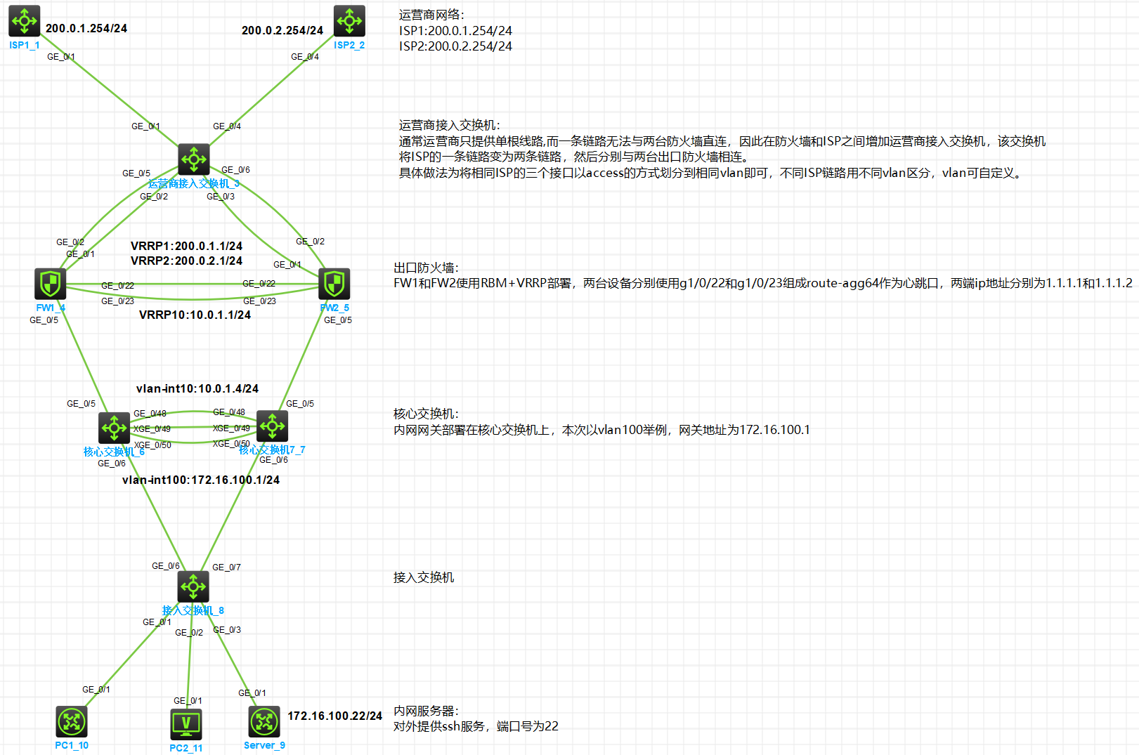
需要加运营商交换机,参考
一、拓扑
二、需求
1、
2、
3、
4、
5、
6、
7、
三、配置思路
1、
2、
3、
4、
5、
四、接口及地址规划
本端接口 | vlan/ip | 补充 | 对端 |
运营商接入交换机 | |||
G1/0/1 | VLAN10 | ISP1 | ISP1 |
G1/0/2 | VLAN10 |
| FW1:G1/0/1 |
G1/0/3 | VLAN10 |
| FW2:G1/0/1 |
G1/0/4 | VLAN20 | ISP2 |
|
G1/0/5 | VLAN20 |
| FW1:G1/0/2 |
G1/0/6 | VLAN20 |
| FW2:G1/0/2 |
出口防火墙FW1 | |||
G1/0/1 | 10.0.0.1/30 | VRRP1:200.0.1.1/24 active |
|
G1/0/2 | 10.0.0.5/30 | VRRP2:200.0.2.1/24 active |
|
G1/0/5 | 10.0.1.2/24 | VRRP10:10.0.1.1/24 active | 核心交换机6:G1/0/5 |
G1/0/22 | Route-agg64,1.1.1.1/30 | HA接口 | FW2:G1/0/22 |
G1/0/23 | FW2:G1/0/23 | ||
出口防火墙FW2 | |||
G1/0/1 | 10.0.0.2/30 | VRRP1:200.0.1.1/24 standby |
|
G1/0/2 | 10.0.0.6/30 | VRRP2:200.0.2.1/24 standby |
|
G1/0/5 | 10.0.1.3/24 | VRRP10:10.0.1.1/24 standby | 核心交换机7:G2/0/5 |
G1/0/22 | Route-agg64,1.1.1.2/30 | HA接口 | FW1:G1/0/22 |
G1/0/23 | FW1:G1/0/23 | ||
核心交换机6-slot1/核心交换机7-slot2(IRF) | |||
G1/0/5 | VLAN10 | Vlan-int:10:10.0.1.4/24 | FW1:G1/0/5 |
G2/0/5 | VLAN10 | FW2:G2/0/5 | |
G1/0/48 | VLAN4000 | BFD MAD检测,1.1.1.5/30 | 核心交换机7:G2/0/48 |
G2/0/48 | VLAN4000 | BFD MAD检测,1.1.1.6/30 | 核心交换机6:G1/0/48 |
XG1/0/49 | IRF-PORT1/1 | IRF接口 | 核心交换机7:XG2/0/49 |
XG1/0/50 | 核心交换机7:XG2/0/50 | ||
XG2/0/49 | IRF-PORT2/2 | IRF接口 | 核心交换机6:XG1/0/49 |
XG2/0/50 | 核心交换机6:XG1/0/50 | ||
G1/0/6 | Bridge-agg100 VLAN100 | Trunk Vlan-int100:172.16.100.1/24 | 接入交换机:G1/0/6 |
G2/0/6 | 接入交换机:G1/0/7 | ||
接入交换机 | |||
G1/0/6 | Bridge-agg100 VLAN100 | Trunk | 核心交换机6:G1/0/6 |
G1/0/7 | 核心交换机7:G2/0/6 | ||
G1/0/1 | Access Vlan100 |
| PC1 |
G1/0/2 |
| PC2 | |
G1/0/3 |
| Server | |
终端 | |||
PC1 | Dhcp自动获取 | 获取固定ip 172.16.100.15 | 接入交换机:G1/0/1 |
PC2 | Dhcp自动获取 | 自动分配 | 接入交换机:G1/0/2 |
Server | 172.16.100.22 | 对外提供ssh服务 | 接入交换机:G1/0/3 |
配置步骤
HCL模拟器工程文件已上传至HCLhub:http://hclhub.h3c.com/project/9466/summary/master?path=README.md&type=text
如连接失效可登录http://hclhub.h3c.com/ 搜索:v7_防火墙_rbm_vrrp_出口主备
(1)
1、
#创建vlan10,并将接口g1/0/1~g1/0/3划分到vlan10 # system-view # vlan 10 port GigabitEthernet 1/0/1 GigabitEthernet 1/0/2 GigabitEthernet 1/0/3 quit # #创建vlan20,并将接口g1/0/4~g1/0/6划分到vlan20 # vlan 20 port GigabitEthernet 1/0/4 GigabitEthernet 1/0/5 GigabitEthernet 1/0/6 quit # #保存配置 save force |
(2)
1、
#创建三层聚合口64,并将接口g1/0/22和接口g1/0/23加入该聚合口。该聚合口将作为FW之间RBM的数据/控制通道,同时为接口配置控制通道IP。 # system-view # sysname FW1 # interface Route-Aggregation64 ip address 1.1.1.1 255.255.255.252 # interface GigabitEthernet1/0/22 port link-aggregation group 64 # interface GigabitEthernet1/0/23 port link-aggregation group 64 #完成RBM配置,指定数据通道为Route-Aggregation64,HA回切时间为10分钟,控制通道本段ip地址为1.1.1.1,对端ip地址为1.1.1.2,本设备作为主管理设备。 remote-backup group data-channel interface Route-Aggregation64 delay-time 10 local-ip 1.1.1.1 remote-ip 1.1.1.2 device-role primary # |
#FW2此部分配置与FW1类似。 # system-view # sysname FW2 # interface Route-Aggregation64 ip address 1.1.1.2 255.255.255.252 # interface GigabitEthernet1/0/22 port link-aggregation group 64 # interface GigabitEthernet1/0/23 port link-aggregation group 64 # remote-backup group data-channel interface Route-Aggregation64 delay-time 10 local-ip 1.1.1.2 remote-ip 1.1.1.1 device-role secondary # |
2、
#ISP只提供了1个公网ip,所以防火墙上行连接到同一组ISP的接口可配置同网段的私网ip地址,将vrrp虚拟地址配置为ISP的ip地址即可,注意配置虚拟IP时需要配置掩码,掩码以ISP给的为准。 #配置VRRP时需要与RBM关联(主设备命令后增加active,反之standby) #因防火墙为双出口,为了保证源进源出,在公网口配置ip last-hop hold。 # interface GigabitEthernet1/0/1 port link-mode route ip address 10.0.0.1 255.255.255.252 vrrp vrid 1 virtual-ip 200.0.1.1 255.255.255.0 active ip last-hop hold # interface GigabitEthernet1/0/2 port link-mode route ip address 10.0.0.5 255.255.255.252 vrrp vrid 2 virtual-ip 200.0.2.1 255.255.255.0 active ip last-hop hold # interface GigabitEthernet1/0/5 port link-mode route ip address 10.0.1.2 255.255.255.0 vrrp vrid 10 virtual-ip 10.0.1.1 255.255.255.0 active # |
#FW2此部分配置与FW1类似。 # interface GigabitEthernet1/0/1 port link-mode route ip address 10.0.0.2 255.255.255.252 vrrp vrid 1 virtual-ip 200.0.1.1 255.255.255.0 standby ip last-hop hold # interface GigabitEthernet1/0/2 port link-mode route ip address 10.0.0.6 255.255.255.252 vrrp vrid 2 virtual-ip 200.0.2.1 255.255.255.0 standby ip last-hop hold # interface GigabitEthernet1/0/5 port link-mode route ip address 10.0.1.3 255.255.255.0 vrrp vrid 10 virtual-ip 10.0.1.1 255.255.255.0 standby # |
3、
#完成nqa配置,用于探测防火墙到各ISP网关地址的连通性,探测方式为icmp,探测间隔为100ms,超时时间为500ms,连续5次不通即探测失败。 # nqa entry isp1 main type icmp-echo destination ip 200.0.1.254 frequency 1000 next-hop ip 200.0.1.254 probe timeout 500 reaction 1 checked-element probe-fail threshold-type consecutive 5 action-type trigger-only # nqa entry isp2 main type icmp-echo destination ip 200.0.2.254 frequency 1000 next-hop ip 200.0.2.254 probe timeout 500 reaction 1 checked-element probe-fail threshold-type consecutive 5 action-type trigger-only # #启动nqa探测,并配置track项与nqa联动 # nqa schedule isp1 main start-time now lifetime forever nqa schedule isp2 main start-time now lifetime forever # track 1 nqa entry isp1 main reaction 1 # track 2 nqa entry isp2 main reaction 1 # #配置缺省路由与track项关联,同时配置去往内网vlan100的回程路由 # ip route-static 0.0.0.0 0 200.0.1.254 track 1 ip route-static 0.0.0.0 0 200.0.2.254 track 2 ip route-static 172.16.100.0 24 10.0.1.4 # |
#FW2此部分配置与FW1类似。 # nqa entry isp1 main type icmp-echo destination ip 200.0.1.254 frequency 1000 next-hop ip 200.0.1.254 probe timeout 500 reaction 1 checked-element probe-fail threshold-type consecutive 5 action-type trigger-only # nqa entry isp2 main type icmp-echo destination ip 200.0.2.254 frequency 1000 next-hop ip 200.0.2.254 probe timeout 500 reaction 1 checked-element probe-fail threshold-type consecutive 5 action-type trigger-only # nqa schedule isp1 main start-time now lifetime forever nqa schedule isp2 main start-time now lifetime forever # track 1 nqa entry isp1 main reaction 1 # track 2 nqa entry isp2 main reaction 1 # ip route-static 0.0.0.0 0 200.0.1.254 track 1 ip route-static 0.0.0.0 0 200.0.2.254 track 2 ip route-static 172.16.100.0 24 10.0.1.4 # |
4、
#配置将内网接口g1/0/5加入trust区域,将ISP1接口g1/0/1加入untrust区域,将ISP2接口g1/0/2加入untrust2区域。 # security-zone name Trust import interface GigabitEthernet1/0/5 quit # security-zone name Untrust import interface GigabitEthernet1/0/1 quit # security-zone name Untrust2 import interface GigabitEthernet1/0/2 quit # |
5、
#配置服务对象组,用于匹配访问tcp目的端口为2222的流量 # object-group service tcp2222 0 service tcp destination eq 2222 quit # #配置nat地址组,用于源地址转换,同时各地址组与接口的VRRP备份组关联 # nat address-group 1 name isp1 address 200.0.1.1 200.0.1.1 vrrp vrid 1 quit # nat address-group 2 name isp2 address 200.0.2.1 200.0.2.1 vrrp vrid 2 quit # nat address-group 5 name trust address 10.0.1.1 10.0.1.1 vrrp vrid 5 quit # nat global-policy #配置名为isp1vlan100server的规则,用于匹配由untrust域访问目的地址为200.0.1.1,目的端口为tcp 2222的流量,匹配上后执行目的地址+端口转换,转换后的目的ip为172.16.100.22,目的端口为tcp 22. rule name isp1vlan100server service tcp2222 source-zone untrust destination-ip host 200.0.1.1 action dnat ip-address 172.16.100.22 local-port 22 rule name isp2vlan100server service tcp2222 source-zone untrust2 destination-ip host 200.0.2.1 action dnat ip-address 172.16.100.22 local-port 22
#配置名为vlan100toserver的规则,用于匹配由trust域访问目的地址为200.0.1.1或200.0.2.1,目的端口为tcp 2222的流量,匹配上后执行目的地址+端口转换,转换后的目的ip为172.16.100.22,目的端口为tcp 22。同时执行源地址转换,转换后的源ip为nat地址组5中的地址。 rule name vlan100toserver service tcp2222 source-zone trust destination-ip host 200.0.1.1 destination-ip host 200.0.2.1 action snat address-group 5 vrrp 5 action dnat ip-address 172.16.100.22 local-port 22
#配置名为vlan100snat1的规则,用于匹配由trust域到untrust域,源地址为172.16.100.0/24的流量,匹配上后执行源地址转换,转换后的源ip为nat地址组1中的地址。 rule name vlan100snat1 source-zone trust destination-zone untrust source-ip subnet 172.16.100.0 24 action snat address-group 1 vrrp 1 rule name vlan100snat2 source-zone trust destination-zone untrust2 source-ip subnet 172.16.100.0 24 action snat address-group 2 vrrp 2 # |
6、
# security-policy ip #创建名为trust2untrust的安全策略规则rule 1,匹配源域为trust,目的域为untrust或untrust2,源地址为172.16.100.0/24的流量,动作为允许。(对应内网vlan100访问互联网的需求) rule 1 name trust2untrust action pass source-zone trust destination-zone untrust destination-zone untrust2 source-ip-subnet 172.16.100.0 255.255.255.0
#创建名为2vlan100server的安全策略规则rule 5,匹配源域为untrust或untrust2,目的域为trust,目的地址为172.16.100.22/32的流量,动作为允许。(对应公网侧访问内网server的需求) rule 5 name 2vlan100server action pass source-zone untrust source-zone untrust2 destination-zone trust destination-ip-host 172.16.100.22
#创建名为nqa的安全策略规则rule 10,匹配源域为local即防火墙自身,目的域为untrust或untrust2的流量,动作为允许。(对应防火墙nqa探测ISP网关地址的需求) rule 10 name nqa action pass source-zone local destination-zone untrust destination-zone untrust2
#创建名为vlan100toserver的安全策略规则rule 15,匹配源域为trust,目的地址为172.16.100.22的流量,动作为允许。(对应内网使用公网地址访问server的需求) rule 15 name vlan100toserver action pass source-zone trust destination-ip-host 172.16.100.22 # |
(4)
1、
#创建业务vlan100 # system-view # sysname ACCESSsw1 # vlan 100 # #配置二层聚合口100,将上行接口g1/0/6和g1/0/7加入二层聚合口100,同时放行vlan100。这里需要按照:创建聚合口、接口空配加入聚合口、进入聚合口完成vlan配置的顺序操作。 # interface Bridge-Aggregation100 quit # interface range GigabitEthernet 1/0/6 GigabitEthernet1/0/7 port link-aggregation group 100 quit # interface Bridge-Aggregation100 port link-type trunk port trunk permit vlan 100 # #配置下行接终端的接口加入vlan100,并开启stp边缘端口 # interface GigabitEthernet1/0/1 port access vlan 100 stp edged-port # interface GigabitEthernet1/0/2 port access vlan 100 stp edged-port # interface GigabitEthernet1/0/3 port access vlan 100 stp edged-port # #保存配置 save force |
配置关键点
1、
#FW1: RBM_P<FW1>dis remote-backup-group status Remote backup group information: Backup mode: Active/standby -----------备份组模式为主/备 Device management role: Primary -----------设备管理状态为主 Device running status: Active -----------设备运行状态为主 Data channel interface: Route-Aggregation64 Local IP: 1.1.1.1 Remote IP: 1.1.1.2 Destination port: 60064 Control channel status: Connected Keepalive interval: 1s Keepalive count: 10 Configuration consistency check interval: 24 hour Configuration consistency check result: Not Performed Configuration backup status: Auto sync enabled Session backup status: Hot backup enabled Delay-time: 10 min Uptime since last switchover: 0 days, 15 hours, 29 minutes Switchover records: Time Status change Cause 2023-02-25 22:31:08 Standby to Active Interface status changed RBM_P<FW1> RBM_P<FW1>dis vrrp IPv4 Virtual Router Information: Running mode : Standard RBM control channel is established VRRP active group status : Master VRRP standby group status: Master Total number of virtual routers : 3 Interface VRID State Running Adver Auth Virtual Pri Timer Type IP ---------------------------------------------------------------------------- GE1/0/1 1 Master 100 100 Not supported 200.0.1.1 GE1/0/2 2 Master 100 100 Not supported 200.0.2.1 GE1/0/5 10 Master 100 100 Not supported 10.0.1.1 RBM_P<FW1> |
#FW2: RBM_S<FW2>dis remote-backup-group status Remote backup group information: Backup mode: Active/standby Device management role: Secondary Device running status: Standby Data channel interface: Route-Aggregation64 Local IP: 1.1.1.2 Remote IP: 1.1.1.1 Destination port: 60064 Control channel status: Connected Keepalive interval: 1s Keepalive count: 10 Configuration consistency check interval: 24 hour Configuration consistency check result: Not Performed Configuration backup status: Auto sync enabled Session backup status: Hot backup enabled Delay-time: 10 min Uptime since last switchover: 0 days, 15 hours, 32 minutes Switchover records: Time Status change Cause 2023-02-25 22:31:08 Active to Standby Interface status changed RBM_S<FW2> RBM_S<FW2>dis vrrp IPv4 Virtual Router Information: Running mode : Standard RBM control channel is established VRRP active group status : Backup VRRP standby group status: Backup Total number of virtual routers : 3 Interface VRID State Running Adver Auth Virtual Pri Timer Type IP ---------------------------------------------------------------------------- GE1/0/1 1 Backup 100 100 Not supported 200.0.1.1 GE1/0/2 2 Backup 100 100 Not supported 200.0.2.1 GE1/0/5 10 Backup 100 100 Not supported 10.0.1.1 RBM_S<FW2> |
- 2024-05-17回答
- 评论(0)
- 举报
-
(0)


编辑答案


亲~登录后才可以操作哦!
确定你的邮箱还未认证,请认证邮箱或绑定手机后进行当前操作
举报
×
侵犯我的权益
×
侵犯了我企业的权益
×
- 1. 您举报的内容是什么?(请在邮件中列出您举报的内容和链接地址)
- 2. 您是谁?(身份证明材料,可以是身份证或护照等证件)
- 3. 是哪家企业?(营业执照,单位登记证明等证件)
- 4. 您与该企业的关系是?(您是企业法人或被授权人,需提供企业委托授权书)
抄袭了我的内容
×
原文链接或出处
诽谤我
×
- 1. 您举报的内容以及侵犯了您什么权益?(请在邮件中列出您举报的内容、链接地址,并给出简短的说明)
- 2. 您是谁?(身份证明材料,可以是身份证或护照等证件)
对根叔社区有害的内容
×
不规范转载
×
举报说明
暂无评论