问题描述:
F1000防火墙设置端口映射后,在公司内部,使用内网地址可以访问,使用外网接口地址访问不通。在外部可以正常使用外网地址访问。
前期配置的其他接口端口映射,内外网都通。
请问如何配置在公司内部,也可以使用外网地址访问系统?
- 2024-11-28提问
- 举报
-
(0)
最佳答案


可以配置一下双向地址转换,nat harping
配置案例:
内网用户通过NAT地址互访配置举例
1. 组网需求
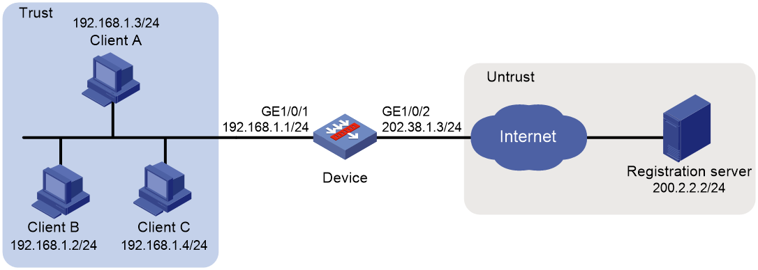
某P2P应用环境中,内网中的客户端首先需要向外网服务器进行注册,外网服务器会记录客户端的IP地址和端口号。如果内网的一个客户端要访问内网的另一个客户端,首先需要向服务器获取对方的IP地址和端口号。
需要实现如下功能:
· 内网客户端可以向外网中的服务器注册,且注册为一个相同的外网地址。
· 内网客户端能够通过从服务器获得的IP地址和端口进行互访。
2. 组网图
图2-7 内网用户通过NAT地址互访配置组网图
3. 配置思路
该需求为典型的P2P模式的NAT hairpin应用,具体配置思路如下。
· 内网中的客户端需要向外网中的服务器注册,因此需要进行源地址转换,可以配置出方向动态地址转换实现。
· 服务器记录客户端的IP地址和端口号,且该地址和端口号是NAT转换后的。由于服务器记录的客户端IP地址和端口号需要供任意源地址访问,因此客户端地址的转换关系必须不关心对端地址,这可以通过配置EIM模式的动态地址转换实现。
4. 配置步骤
(1) 配置接口IP地址
# 根据组网图中规划的信息,配置各接口的IP地址,具体配置步骤如下。
<Device> system-view
[Device] interface gigabitethernet 1/0/1
[Device-GigabitEthernet1/0/1] ip address 192.168.1.1 24
[Device-GigabitEthernet1/0/1] quit
请参考以上步骤配置其他接口的IP地址,具体配置步骤略。
(2) 将接口加入安全域
# 请根据组网图中规划的信息,将接口加入对应的安全域,具体配置步骤如下。
[Device] security-zone name trust
[Device-security-zone-Trust] import interface gigabitethernet 1/0/1
[Device-security-zone-Trust] quit
[Device] security-zone name untrust
[Device-security-zone-Untrust] import interface gigabitethernet 1/0/2
[Device-security-zone-Untrust] quit
(3) 配置静态路由
本举例仅以静态路由方式配置路由信息。实际组网中,请根据具体情况选择相应的路由配置方式。
# 请根据组网图中规划的信息,配置静态路由,本举例假设到达Server所在网络的下一跳IP地址为202.38.1.1,实际使用中请以具体组网情况为准,具体配置步骤如下。
[Device] ip route-static 200.2.2.0 24 202.38.1.1
(4) 配置安全策略
# 配置名称为trust-untrust的安全策略,保证Trust安全域内的Host可以访问Untrust安全域内的Server,具体配置步骤如下。
[Device] security-policy ip
[Device-security-policy-ip] rule name trust-untrust
[Device-security-policy-ip-1-trust-untrust] source-zone trust
[Device-security-policy-ip-1-trust-untrust] destination-zone untrust
[Device-security-policy-ip-1-trust-untrust] source-ip-subnet 192.168.1.0 24
[Device-security-policy-ip-1-trust-untrust] destination-ip-host 200.2.2.2
[Device-security-policy-ip-1-trust-untrust] action pass
[Device-security-policy-ip-1-trust-untrust] quit
# 配置名称为trust-trust的安全策略,保证Trust安全域内的Host可以互访,具体配置步骤如下。
[Device-security-policy-ip] rule name trust-trust
[Device-security-policy-ip-2-trust-trust] source-zone trust
[Device-security-policy-ip-2-trust-trust] destination-zone trust
[Device-security-policy-ip-2-trust-trust] source-ip-host 202.38.1.3
[Device-security-policy-ip-2-trust-trust] destination-ip-subnet 192.168.1.0 24
[Device-security-policy-ip-2-trust-trust] action pass
[Device-security-policy-ip-2-trust-trust] quit
[Device-security-policy-ip] quit
(5) 配置NAT功能
# 配置地址对象组obj1,仅允许对192.168.1.0/24网段的用户报文进行地址转换。
[Device] object-group ip address obj1
[Device-obj-grp-ip-obj1] network subnet 192.168.1.0 24
[Device-obj-grp-ip-obj1] quit
# 配置全局NAT规则,通过Easy IP方式对内网访问外网的报文进行源地址转换,因为多个内部主机共用一个外网地址,因此需要配置为PAT方式,即转换过程中使用端口信息。
[Device] nat global-policy
[Device-nat-global-policy] rule name rule1
[Device-nat-global-policy-rule-rule1] source-zone trust
[Device-nat-global-policy-rule-rule1] destination-zone untrust
[Device-nat-global-policy-rule-rule1] source-ip obj1
[Device-nat-global-policy-rule-rule1] action snat easy-ip
[Device-nat-global-policy-rule-rule1] quit
[Device-nat-global-policy] quit
# 配置ACL 2000,允许对内部网络中192.168.1.0/24网段的报文进行地址转换。
[Device] acl basic 2000
[Device-acl-ipv4-basic-2000] rule permit source 192.168.1.0 0.0.0.255
[Device-acl-ipv4-basic-2000] quit
# 配置PAT方式下的地址转换模式为EIM,即只要是来自相同源地址和源端口号的且匹配ACL 2000的报文,不论其目的地址是否相同,通过PAT转换后,其源地址和源端口号都被转换为同一个外部地址和端口号。
[Device] nat mapping-behavior endpoint-independent acl 2000
5. 验证配置
# 以上配置完成后,Host A、Host B和Host C 分别向外网服务器注册之后,它们之间可以相互访问。通过查看如下显示信息,可以验证以上配置成功。
[Device] display nat all
NAT global-policy information:
Totally 2 NAT global-policy rules.
Rule name: rule1
Type : nat
SrcIP object group : obj1
Source-zone name : trust
Destination-zone name : untrust
SNAT action:
Easy-IP
Reversible: N
Port-preserved: N
NAT counting : 0
Config status: Active
NAT logging:
Log enable : Disabled
Flow-begin : Disabled
Flow-end : Disabled
Flow-active : Disabled
Port-block-assign : Disabled
Port-block-withdraw : Disabled
Alarm : Disabled
NO-PAT IP usage : Disabled
NAT mapping behavior:
Mapping mode : Endpoint-Independent
ACL : 2000
Config status: Active
NAT ALG:
DNS : Enabled
FTP : Enabled
H323 : Disabled
ICMP-ERROR : Enabled
ILS : Disabled
MGCP : Disabled
NBT : Disabled
PPTP : Enabled
RTSP : Enabled
RSH : Disabled
SCCP : Disabled
SIP : Disabled
SQLNET : Disabled
TFTP : Disabled
XDMCP : Disabled
Static NAT load balancing: Disabled
NAT link-switch recreate-session: Disabled
NAT configuration-for-new-connection: Disabled
NAT global-policy compatible-previous-version rule-type ipv4-snat-and-dnat translate-before-secp : Disabled
NAT gratuitous-arp: Enabled
# 通过以下显示命令,可以看到Client A访问Client B时生成NAT会话信息。
[Device] display nat session verbose
Slot 1:
Initiator:
Source IP/port: 192.168.1.3/44929
Destination IP/port: 202.38.1.3/1
DS-Lite tunnel peer: -
VPN instance/VLAN ID/Inline ID: -/-/-
Protocol: UDP(17)
Inbound interface: GigabitEthernet1/0/1
Source security zone: Trust
Responder:
Source IP/port: 192.168.1.2/69
Destination IP/port: 202.38.1.3/1024
DS-Lite tunnel peer: -
VPN instance/VLAN ID/Inline ID: -/-/-
Protocol: UDP(17)
Inbound interface: GigabitEthernet1/0/1
Source security zone: Trust
State: UDP_READY
Application: TFTP
Rule ID: -/-/-
Rule name:
Start time: 2012-08-15 15:53:36 TTL: 46s
Initiator->Responder: 1 packets 56 bytes
Responder->Initiator: 1 packets 72 bytes
Total sessions found: 1
- 2024-11-28回答
- 评论(2)
- 举报
-
(0)
如何配置?

内网口开一下nat hairpin功能
int ****
nat hairpin enable
- 2024-11-28回答
- 评论(2)
- 举报
-
(0)
请问在哪儿配置?
编辑答案


亲~登录后才可以操作哦!
确定你的邮箱还未认证,请认证邮箱或绑定手机后进行当前操作
举报
×
侵犯我的权益
×
侵犯了我企业的权益
×
- 1. 您举报的内容是什么?(请在邮件中列出您举报的内容和链接地址)
- 2. 您是谁?(身份证明材料,可以是身份证或护照等证件)
- 3. 是哪家企业?(营业执照,单位登记证明等证件)
- 4. 您与该企业的关系是?(您是企业法人或被授权人,需提供企业委托授权书)
抄袭了我的内容
×
原文链接或出处
诽谤我
×
- 1. 您举报的内容以及侵犯了您什么权益?(请在邮件中列出您举报的内容、链接地址,并给出简短的说明)
- 2. 您是谁?(身份证明材料,可以是身份证或护照等证件)
对根叔社区有害的内容
×
不规范转载
×
举报说明


配置和案例发在上面了。可以参考一下