
最佳答案


一、基础概念理解
链路聚合类型对比
类型 | 应用场景 | 配置接口 | 转发特性 |
|---|---|---|---|
二层聚合 | 连接交换机或接入层 | Bridge-Aggregation | 仅二层转发,不带IP |
三层聚合 | 路由接口或网关 | Route-Aggregation | 三层路由接口,需配IP |
二、二层链路聚合配置(Bridge-Aggregation)
方案1:静态二层聚合(手工模式,最常用)
# 1. 创建二层聚合组
system-view
interface bridge-aggregation 10
description To-Switch-Trunk
link-aggregation mode static
port link-type trunk
port trunk permit vlan all
quit
# 2. 配置物理端口(以Ten-GigabitEthernet 1/0/1-2为例)
interface range ten-gigabitethernet 1/0/1 to ten-gigabitethernet 1/0/2
port link-aggregation group 10
# 如果需要Trunk,在聚合组配置即可,这里不需要重复配置
quit
# 3. 可选:配置负载分担算法
link-aggregation load-sharing mode destination-ip source-ip destination-port source-port
方案2:动态LACP聚合(推荐,自动检测)
# 1. 创建LACP聚合组
system-view
interface bridge-aggregation 20
description LACP-to-Core
link-aggregation mode dynamic
port link-type trunk
port trunk permit vlan 10 20 30
lacp system-priority 100
quit
# 2. 配置物理端口
interface range ten-gigabitethernet 1/0/3 to ten-gigabitethernet 1/0/4
port link-aggregation group 20
lacp period short # 快速模式,默认是30秒,short是1秒
quit
三、三层链路聚合配置(Route-Aggregation)
方案1:静态三层聚合
# 1. 创建三层聚合接口
system-view
interface route-aggregation 100
description Uplink-to-Router
ip address 192.168.100.1 255.255.255.252
link-aggregation mode static
quit
# 2. 将物理端口加入聚合组
interface range ten-gigabitethernet 1/0/5 to ten-gigabitethernet 1/0/6
port link-aggregation group 100
quit
方案2:动态LACP三层聚合
# 1. 创建LACP三层聚合接口
system-view
interface route-aggregation 101
description LACP-Uplink
ip address 10.1.1.1 255.255.255.0
link-aggregation mode dynamic
quit
# 2. 配置物理端口
interface range ten-gigabitethernet 1/0/7 to ten-gigabitethernet 1/0/8
port link-aggregation group 101
lacp period short
quit
四、完整配置示例
示例1:双上行到两台核心交换机(跨设备链路聚合)
# 配置M-LAG(跨设备链路聚合),需要两台S5830
# 设备A配置
system-view
# 创建M-LAG域
m-lag
system-mac 0001-0001-0001
system-number 1
system-priority 100
quit
# 配置M-LAG Peer-Link(用于M-LAG设备间同步)
interface bridge-aggregation 1
port link-type trunk
port trunk permit vlan all
link-aggregation mode dynamic
quit
interface ten-gigabitethernet 1/0/49
port link-aggregation group 1
quit
interface ten-gigabitethernet 1/0/50
port link-aggregation group 1
quit
# 创建M-LAG聚合组
interface bridge-aggregation 10
port link-type trunk
port trunk permit vlan 10 20
m-lag group 10
quit
# 加入物理端口
interface ten-gigabitethernet 1/0/1
port link-aggregation group 10
quit
示例2:三层聚合网关配置
# 创建三层聚合作为VLAN网关
system-view
vlan 100
name Server-VLAN
quit
interface route-aggregation 1
description Server-Farm-Gateway
ip address 172.16.100.1 255.255.255.0
link-aggregation mode dynamic
quit
# 将三层聚合接口加入VLAN
vlan 100
port route-aggregation 1
quit
五、高级配置选项
1. 负载分担算法配置
# 查看当前负载分担模式
display link-aggregation load-sharing mode
# 设置基于流的负载分担
link-aggregation global load-sharing mode ?
# 可选模式:
# destination-ip 目的IP
# destination-mac 目的MAC
# destination-port 目的端口
# source-ip 源IP
# source-mac 源MAC
# source-port 源端口
# enhanced 增强模式
# 示例:基于源目的IP和端口
link-aggregation global load-sharing mode destination-ip source-ip destination-port source-port
# 针对特定聚合组设置
interface bridge-aggregation 10
link-aggregation load-sharing mode destination-ip source-ip
quit
2. 链路故障检测优化
# 配置BFD快速检测
bfd
quit
interface bridge-aggregation 10
lacp fast-timeout enable
bfd min-transmit-interval 100
bfd min-receive-interval 100
bfd detect-multiplier 3
quit
3. 链路聚合安全配置
# 开启LACP系统保护
lacp system-protection enable
# 配置LACP超时时间
interface ten-gigabitethernet 1/0/1
lacp period short # 短超时(1秒)
# lacp period long # 长超时(30秒,默认)
quit
六、配置验证与诊断
1. 查看聚合状态
# 查看所有聚合组摘要
display link-aggregation summary
# 查看特定聚合组详细信息
display link-aggregation verbose bridge-aggregation 10
display link-aggregation verbose route-aggregation 100
# 查看成员端口状态
display interface bridge-aggregation 10
display interface route-aggregation 100
# 查看LACP状态
display lacp system-id
display lacp statistics interface bridge-aggregation 10
2. 查看流量统计
# 查看聚合组流量
display counters interface bridge-aggregation 10
display counters rate interface bridge-aggregation 10
# 查看负载分担情况
display link-aggregation load-sharing interface bridge-aggregation 10
3. 调试命令
# 开启调试信息(谨慎在生产环境使用)
debugging lacp all
terminal debugging
terminal monitor
# 查看日志
display logbuffer
七、故障排查指南
常见问题1:聚合组无法UP
# 1. 检查物理链路
display interface ten-gigabitethernet 1/0/1 brief
# 2. 检查端口配置一致性
display current-configuration interface ten-gigabitethernet 1/0/1
display current-configuration interface ten-gigabitethernet 1/0/2
# 3. 检查LACP协商状态
display lacp statistics interface bridge-aggregation 10
常见问题2:流量不均衡
# 1. 检查负载分担模式
display link-aggregation load-sharing mode
# 2. 检查流量统计
display counters interface bridge-aggregation 10
reset counters interface bridge-aggregation 10
# 等待一段时间后再次查看
display counters interface bridge-aggregation 10
八、最佳实践建议
1. 端口选择原则
# 使用相同速度的端口
# 使用相邻的端口(便于管理)
# 避免跨线卡的聚合(如果支持,确保性能)
interface range ten-gigabitethernet 1/0/1 to ten-gigabitethernet 1/0/4
interface range ten-gigabitethernet 2/0/1 to ten-gigabitethernet 2/0/4
2. VLAN配置建议
# 在聚合组上配置VLAN,而不是单个端口
interface bridge-aggregation 10
port link-type trunk
port trunk permit vlan 10 20 30
port trunk pvid vlan 10
quit
3. 聚合组命名规范
# 创建描述性名称
interface bridge-aggregation 10
description TO-CORE-SW_LACP
quit
interface route-aggregation 100
description TO-FIREWALL_STATIC
quit
九、配置文件示例
完整的二层LACP聚合配置
sysname S5830-1
vlan 10
name Data
vlan 20
name Voice
vlan 30
name Management
interface bridge-aggregation 1
description UPLINK-TO-CORE
link-aggregation mode dynamic
port link-type trunk
port trunk permit vlan 10 20 30
stp cost 20000
stp instance 0 cost 20000
link-aggregation load-sharing mode destination-ip source-ip
interface ten-gigabitethernet 1/0/49
port link-aggregation group 1
lacp period short
interface ten-gigabitethernet 1/0/50
port link-aggregation group 1
lacp period short
link-aggregation global load-sharing mode destination-ip source-ip destination-port source-port
lacp system-priority 32768
完整的三层静态聚合配置
interface route-aggregation 1
description ROUTED-LINK-TO-FW
ip address 10.1.1.2 255.255.255.252
link-aggregation mode static
mtu 9216
ip mtu 1500
ospf cost 10
ospf network-type broadcast
interface ten-gigabitethernet 1/0/47
port link-aggregation group 1
mtu 9216
interface ten-gigabitethernet 1/0/48
port link-aggregation group 1
mtu 9216
十、重要注意事项
端口一致性要求:
相同速率和双工模式
相同的VLAN配置
相同的STP设置
相同的QoS配置
最大聚合组限制:
S5830支持的最大聚合组数:128个
每个聚合组最大端口数:8个
实际限制请参考具体型号规格
LACP最佳实践:
两端都配置LACP模式
使用相同的LACP系统优先级
配置快速超时(short)以加快故障检测
故障切换时间:
静态聚合:秒级收敛
LACP长超时:30-90秒
LACP短超时:3-9秒
结合BFD:毫秒级
保存配置:
save force
如果遇到具体问题,请提供以下信息以便进一步诊断:
display version输出
具体的端口号和配置
对端设备型号和配置
错误信息或故障现象
- 2026-01-23回答
- 评论(0)
- 举报
-
(0)


创建二层聚合接口1。
[DeviceA] interface bridge-aggregation 1
[DeviceA-Bridge-Aggregation1] quit
# 分别将端口GigabitEthernet1/0/1和GigabitEthernet1/0/2加入到聚合组1中。
[DeviceA] interface gigabitethernet 1/0/1
[DeviceA-gigabitethernet1/0/1] port link-aggregation group 1
[DeviceA-gigabitethernet1/0/1] quit
[DeviceA] interface gigabitethernet 1/0/2
[DeviceA-gigabitethernet1/0/2] port link-aggregation group 1
[DeviceA-gigabitethernet1/0/2] quit
创建三层聚合口1
interface Route-Aggregation 1
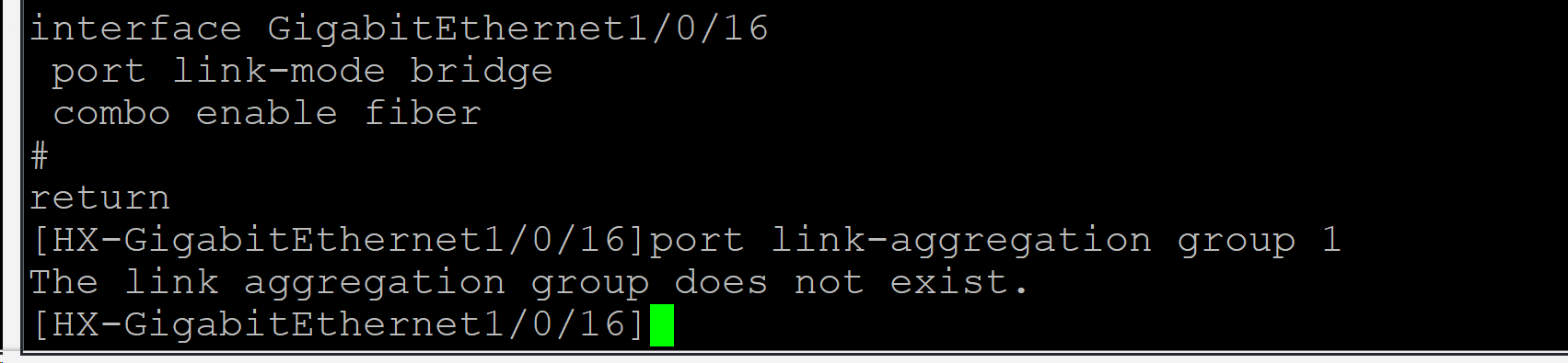
interface GigabitEthernet 1/0/16
port link-mode route 因为交换机接口一般都是二层口,需要先改成三层口,要不然加不进三层聚合组
port link-aggregation group 1
二层口如果不变成三层口,加聚合组,会出现的情况 如下图
- 2026-01-23回答
- 评论(0)
- 举报
-
(0)
暂无评论

您好,参考
1.8.1 二层静态聚合配置举例
1. 组网需求
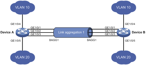
l Device A与Device B通过各自的以太网端口GigabitEthernet1/0/1~GigabitEthernet1/0/3相互连接。
l 在Device A和Device B上分别配置静态链路聚合组,并使两端的VLAN 10和VLAN 20之间分别互通。
l 通过按照报文的源MAC地址和目的MAC地址进行聚合负载分担的方式,来实现数据流量在各成员端口间的负载分担。
2. 组网图
图1-5 静态聚合配置组网图
3. 配置步骤
(1) 配置Device A
# 创建VLAN 10,并将端口GigabitEthernet1/0/4加入到该VLAN中。
<DeviceA> system-view
[DeviceA] vlan 10
[DeviceA-vlan10] port gigabitEthernet 1/0/4
[DeviceA-vlan10] quit
# 创建VLAN 20,并将端口GigabitEthernet1/0/5加入到该VLAN中。
[DeviceA] vlan 20
[DeviceA-vlan20] port gigabitEthernet 1/0/5
[DeviceA-vlan20] quit
# 创建二层聚合接口1。
[DeviceA] interface bridge-aggregation 1
[DeviceA-Bridge-Aggregation1] quit
# 分别将端口GigabitEthernet1/0/1至 GigabitEthernet1/0/3加入到聚合组1中。
[DeviceA] interface gigabitethernet 1/0/1
[DeviceA-gigabitethernet1/0/1] port link-aggregation group 1
[DeviceA-gigabitethernet1/0/1] quit
[DeviceA] interface gigabitethernet 1/0/2
[DeviceA-gigabitethernet1/0/2] port link-aggregation group 1
[DeviceA-gigabitethernet1/0/2] quit
[DeviceA] interface gigabitethernet 1/0/3
[DeviceA-gigabitethernet1/0/3] port link-aggregation group 1
[DeviceA-gigabitethernet1/0/3] quit
# 配置二层聚合接口1为Trunk端口,并允许VLAN 10和20的报文通过。
![]()
该配置将被自动同步到聚合组1内的所有成员端口上。
[DeviceA] interface bridge-aggregation 1
[DeviceA-Bridge-Aggregation1] port link-type trunk
[DeviceA-Bridge-Aggregation1] port trunk permit vlan 10 20
Please wait... Done.
Configuring GigabitEthernet1/0/1... Done.
Configuring GigabitEthernet1/0/2... Done.
Configuring GigabitEthernet1/0/3... Done.
[DeviceA-Bridge-Aggregation1] quit
# 配置全局按照报文的源MAC地址和目的MAC地址进行聚合负载分担。
[DeviceA] link-aggregation load-sharing mode source-mac destination-mac
(2) 配置Device B
Device B的配置与Device A相似,配置过程略。
(3) 检验配置效果
# 查看Device A上所有聚合组的摘要信息。
[DeviceA] display link-aggregation summary
Aggregation Interface Type:
BAGG -- Bridge-Aggregation, RAGG -- Route-Aggregation
Aggregation Mode: S -- Static, D -- Dynamic
Loadsharing Type: Shar -- Loadsharing, NonS -- Non-Loadsharing
Actor System ID: 0x8000, 000f-e2ff-0001
AGG AGG Partner ID Select Unselect Share
Interface Mode Ports Ports Type
-------------------------------------------------------------------------------
BAGG1 S none 3 0 Shar
以上信息表明,聚合组1为负载分担类型的静态聚合组,包含有三个选中端口。
# 查看Device A上全局采用的聚合负载分担类型。
[DeviceA] display link-aggregation load-sharing mode
Link-Aggregation Load-Sharing Mode:
destination-mac address, source-mac address
以上信息表明,所有聚合组都按照报文的源MAC地址和目的MAC地址进行聚合负载分担。
1.8.2 动态聚合配置举例
1. 组网需求
l Device A与Device B通过各自的以太网端口GigabitEthernet1/0/1~GigabitEthernet1/0/3相互连接。
l 在Device A和Device B上分别配置动态链路聚合组,并使两端的VLAN 10和VLAN 20之间分别互通。
l 通过按照报文的源MAC地址和目的MAC地址进行聚合负载分担的方式,来实现数据流量在各成员端口间的负载分担。
2. 组网图
图1-6 动态聚合配置组网图
3. 配置步骤
(1) 配置Device A
# 创建VLAN 10,并将端口GigabitEthernet1/0/4加入到该VLAN中。
<DeviceA> system-view
[DeviceA] vlan 10
[DeviceA-vlan10] port gigabitEthernet 1/0/4
[DeviceA-vlan10] quit
# 创建VLAN 20,并将端口GigabitEthernet1/0/5加入到该VLAN中。
[DeviceA] vlan 20
[DeviceA-vlan20] port gigabitEthernet 1/0/5
[DeviceA-vlan20] quit
# 创建二层聚合接口1,并配置该接口为动态聚合模式。
[DeviceA] interface bridge-aggregation 1
[DeviceA-Bridge-Aggregation1] link-aggregation mode dynamic
[DeviceA-Bridge-Aggregation1] quit
# 分别将端口GigabitEthernet1/0/1至 GigabitEthernet1/0/3加入到聚合组1中。
[DeviceA] interface gigabitethernet 1/0/1
[DeviceA-gigabitethernet1/0/1] port link-aggregation group 1
[DeviceA-gigabitethernet1/0/1] quit
[DeviceA] interface gigabitethernet 1/0/2
[DeviceA-gigabitethernet1/0/2] port link-aggregation group 1
[DeviceA-gigabitethernet1/0/2] quit
[DeviceA] interface gigabitethernet 1/0/3
[DeviceA-gigabitethernet1/0/3] port link-aggregation group 1
[DeviceA-gigabitethernet1/0/3] quit
# 配置二层聚合接口1为Trunk端口,并允许VLAN 10和20的报文通过。
![]()
该配置将被自动同步到聚合组1内的所有成员端口上。
[DeviceA] interface bridge-aggregation 1
[DeviceA-Bridge-Aggregation1] port link-type trunk
[DeviceA-Bridge-Aggregation1] port trunk permit vlan 10 20
Please wait... Done.
Configuring GigabitEthernet1/0/1... Done.
Configuring GigabitEthernet1/0/2... Done.
Configuring GigabitEthernet1/0/3... Done.
[DeviceA-Bridge-Aggregation1] quit
# 配置全局按照报文的源MAC地址和目的MAC地址进行聚合负载分担。
[DeviceA] link-aggregation load-sharing mode source-mac destination-mac
(2) 配置Device B
Device B的配置与Device A相似,配置过程略。
(3) 检验配置效果
# 查看Device A上所有聚合组的摘要信息。
[DeviceA] display link-aggregation summary
Aggregation Interface Type:
BAGG -- Bridge-Aggregation, RAGG -- Route-Aggregation
Aggregation Mode: S -- Static, D -- Dynamic
Loadsharing Type: Shar -- Loadsharing, NonS -- Non-Loadsharing
Actor System ID: 0x8000, 000f-e2ff-0001
AGG AGG Partner ID Select Unselect Share
Interface Mode Ports Ports Type
-------------------------------------------------------------------------------
BAGG1 D 0x8000, 000f-e2ff-0002 3 0 Shar
以上信息表明,聚合组1为负载分担类型的二层动态聚合组,包含有三个选中端口。
# 查看Device A上全局采用的聚合负载分担类型。
[DeviceA] display link-aggregation load-sharing mode
Link-Aggregation Load-Sharing Mode:
destination-mac address, source-mac address
以上信息表明,所有聚合组都按照报文的源MAC地址和目的MAC地址进行聚合负载分担。
- 2026-01-23回答
- 评论(0)
- 举报
-
(0)
暂无评论
编辑答案


亲~登录后才可以操作哦!
确定你的邮箱还未认证,请认证邮箱或绑定手机后进行当前操作
举报
×
侵犯我的权益
×
侵犯了我企业的权益
×
- 1. 您举报的内容是什么?(请在邮件中列出您举报的内容和链接地址)
- 2. 您是谁?(身份证明材料,可以是身份证或护照等证件)
- 3. 是哪家企业?(营业执照,单位登记证明等证件)
- 4. 您与该企业的关系是?(您是企业法人或被授权人,需提供企业委托授权书)
抄袭了我的内容
×
原文链接或出处
诽谤我
×
- 1. 您举报的内容以及侵犯了您什么权益?(请在邮件中列出您举报的内容、链接地址,并给出简短的说明)
- 2. 您是谁?(身份证明材料,可以是身份证或护照等证件)
对根叔社区有害的内容
×
不规范转载
×
举报说明
暂无评论