MPLS l3 vpn
- 0关注
- 1收藏,1797浏览
问题描述:
ce1跟pe1之间采用ospf、isis、静态路由协议需要怎么配置互相引入啊?
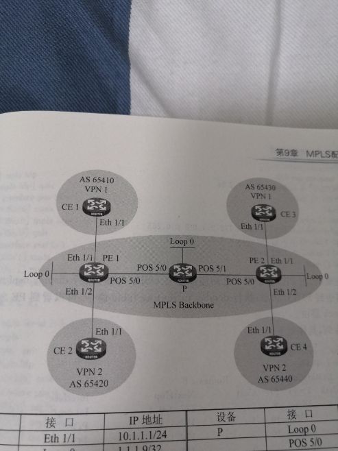
组网及组网描述:

- 2020-01-04提问
- 举报
-
(0)
最佳答案

路由引入:
1.2配置需求
SWA、SWB、SWC、SWD运行OSPF。SWC、SWE和SWG运行静态路,并将整个自治系统划分为3个区域。其中Switch A和Switch B作为ABR来转发区域之间的路由。Switch C上配置为ASBR引入外部路由(静态路由),且路由信息可正确的在AS内传播。
2 组网图

配置步骤
3.1 SWA配置
#创建vlan100和vlan200,并把G1/0/1口加入vlan100、1/0/2口加入vlan200 ,并且配置vlan100和vlan200 的虚接口地址
<SWA>system-view
System View: return to User View with Ctrl+Z.
[SWA]vlan 100
[SWA-vlan100]port GigabitEthernet 1/0/1
[SWA-vlan100]quit
[SWA]vlan 200
[SWA-vlan200]port GigabitEthernet 1/0/2
[SWA-vlan200]quit
[SWA]interface vlan 100
[SWA-Vlan-interface100]ip address 192.168.0.1 255.255.255.0
[SWA-Vlan-interface100]quit
[SWA]interface vlan 200
[SWA-Vlan-interface200]ip address 192.168.1.1 255.255.255.0
[SWA-Vlan-interface200]quit
#启动ospf协议,并设置路由器的router id
[SWA]ospf 1 router-id 192.168.1.1
#配置区域0并且发布网段
[SWA-ospf-1]area 0
[SWA-ospf-1-area-0.0.0.0]network 192.168.0.0 0.0.0.255
[SWA-ospf-1-area-0.0.0.0]quit
#配置区域1并且发布网段
[SWA-ospf-1]area 1
[SWA-ospf-1-area-0.0.0.1]network 192.168.1.0 0.0.0.255
[SWA-ospf-1-area-0.0.0.1]quit
[SWA-ospf-1]quit
#保存配置
[SWA]save force
3.2 SWB配置
#创建vlan100和vlan200,并把G1/0/1口加入vlan100、1/0/2口加入vlan200 ,并且配置vlan100和vlan200 的虚接口地址
<SWB>system-view
System View: return to User View with Ctrl+Z.
[SWB]vlan 100
[SWB-vlan100]port GigabitEthernet 1/0/1
[SWB-vlan100]quit
[SWB]vlan 200
[SWB-vlan200]port GigabitEthernet 1/0/2
[SWB-vlan200]quit
[SWB]interface vlan 100
[SWB-Vlan-interface100]ip address 192.168.0.2 255.255.255.0
[SWB-Vlan-interface100]quit
[SWB]interface vlan 200
[SWB-Vlan-interface200]ip address 192.168.2.1 255.255.255.0
[SWB-Vlan-interface200]quit
#启动ospf协议,并设置路由器的router id
[SWB]ospf 1 router-id 192.168.2.1
#配置区域0并且发布网段
[SWB-ospf-1]area 0
[SWB-ospf-1-area-0.0.0.0]network 192.168.0.0 0.0.0.255
[SWB-ospf-1-area-0.0.0.0]quit
#配置区域2并且发布网段
[SWB-ospf-1]area 2
[SWB-ospf-1-area-0.0.0.2]network 192.168.2.0 0.0.0.255
[SWB-ospf-1-area-0.0.0.2]quit
[SWB-ospf-1]quit
#保存配置
[SWB]save force
3.3 SWC配置
#创建vlan200和vlan300,并把G1/0/1口加入vlan300、1/0/2口加入vlan200 ,并且配置vlan300和vlan200 的虚接口地址
<SWC>system-view
System View: return to User View with Ctrl+Z.
[SWC]vlan 300
[SWC-vlan300]port GigabitEthernet 1/0/1
[SWC-vlan300]quit
[SWC]vlan 200
[SWC-vlan200]port GigabitEthernet 1/0/2
[SWC-vlan200]quit
[SWC]interface vlan 300
[SWC-Vlan-interface300]ip address 172.16.1.1 255.255.255.0
[SWC-Vlan-interface300]quit
[SWC]interface vlan 200
[SWC-Vlan-interface200]ip address 192.168.1.2 255.255.255.0
[SWC-Vlan-interface200]quit
#配置到10.10.10.0网段的静态路由,下一跳指向172.16.1.2
[SWC]ip route-static 10.10.10.0 24 172.16.1.2
#启动ospf协议,并设置路由器的router id
[SWC]ospf 1 router-id 192.168.1.2
#配置区域1并且发布网段
[SWC-ospf-1]area 1
[SWC-ospf-1-area-0.0.0.1]network 192.168.1.0 0.0.0.255
[SWC-ospf-1-area-0.0.0.1]network 172.16.1.0 0.0.0.255
[SWC-ospf-1-area-0.0.0.1]quit
#在ospf中引入静态路由
[SWC-ospf-1]import-route static
[SWC-ospf-1]quit
#保存配置
[SWC]save force
3.4 SWD配置
#创建vlan200和vlan300,并把G1/0/1口加入vlan300、1/0/2口加入vlan200 ,并且配置vlan300和vlan200 的虚接口地址
<SWD>system-view
System View: return to User View with Ctrl+Z.
[SWD]vlan 300
[SWD-vlan300]port GigabitEthernet 1/0/1
[SWD-vlan300]quit
[SWD]vlan 200
[SWD-vlan200]port GigabitEthernet 1/0/2
[SWD-vlan200]quit
[SWD]interface vlan 300
[SWD-Vlan-interface300]ip address 172.17.1.1 255.255.255.0
[SWD-Vlan-interface300]quit
[SWD]interface vlan 200
[SWD-Vlan-interface200]ip address 192.168.2.2 255.255.255.0
[SWD-Vlan-interface200]quit
#启动ospf协议,并设置路由器的router id
[SWD]ospf 1 router-id 192.168.2.2
#配置区域1并且发布网段
[SWD-ospf-1]area 2
[SWD-ospf-1-area-0.0.0.2]network 192.168.2.0 0.0.0.255
[SWD-ospf-1-area-0.0.0.2]network 172.17.1.0 0.0.0.255
[SWD-ospf-1-area-0.0.0.2]quit
[SWD-ospf-1]quit
#保存配置
[SWD]save force
3.5 SWE配置
#创建vlan300和vlan400,并把G1/0/1口加入vlan300、1/0/2口加入vlan400 ,并且配置vlan300和vlan400 的虚接口地址
<SWE>system-view
System View: return to User View with Ctrl+Z.
[SWE]vlan 300
[SWE-vlan300]port GigabitEthernet 1/0/1
[SWE-vlan300]quit
[SWE]vlan 400
[SWE-vlan400]port GigabitEthernet 1/0/2
[SWE-vlan400]quit
[SWE]interface vlan 300
[SWE-Vlan-interface300]ip address 172.16.1.2 255.255.255.0
[SWE-Vlan-interface300]quit
[SWE]interface vlan 400
[SWE-Vlan-interface400]ip address 10.10.10.1 255.255.255.0
[SWE-Vlan-interface400]quit
#配置默认路由指向172.16.1.1
[SWE]ip route-static 0.0.0.0 0 172.16.1.1
[SWE]save force
3.6 验证配置
#查看Switch A的路由表信息,有到172.16.1.0、172.17.1.0、192.168.2.0的路由以及学习到外部引入的静态路由
<SWA>display ip routing-table
Destinations : 20 Routes : 20
Destination/Mask Proto Pre Cost NextHop Interface
0.0.0.0/32 Direct 0 0 127.0.0.1 InLoop0
10.10.10.0/24 O_ASE2 150 1 192.168.1.2 Vlan200
127.0.0.0/8 Direct 0 0 127.0.0.1 InLoop0
127.0.0.0/32 Direct 0 0 127.0.0.1 InLoop0
127.0.0.1/32 Direct 0 0 127.0.0.1 InLoop0
127.255.255.255/32 Direct 0 0 127.0.0.1 InLoop0
172.16.1.0/24 O_INTRA 10 2 192.168.1.2 Vlan200
172.17.1.0/24 O_INTER 10 3 192.168.0.2 Vlan100
192.168.0.0/24 Direct 0 0 192.168.0.1 Vlan100
192.168.0.0/32 Direct 0 0 192.168.0.1 Vlan100
192.168.0.1/32 Direct 0 0 127.0.0.1 InLoop0
192.168.0.255/32 Direct 0 0 192.168.0.1 Vlan100
192.168.1.0/24 Direct 0 0 192.168.1.1 Vlan200
192.168.1.0/32 Direct 0 0 192.168.1.1 Vlan200
192.168.1.1/32 Direct 0 0 127.0.0.1 InLoop0
192.168.1.255/32 Direct 0 0 192.168.1.1 Vlan200
192.168.2.0/24 O_INTER 10 2 192.168.0.2 Vlan100
224.0.0.0/4 Direct 0 0 0.0.0.0 NULL0
224.0.0.0/24 Direct 0 0 0.0.0.0 NULL0
255.255.255.255/32 Direct 0 0 127.0.0.1 InLoop0
# PC1 ping PC2 正常通信
C:\Users\mfw2656>ping 172.17.1.2
Ping 172.17.1.2 (172.17.1.2): 56 data bytes, press CTRL_C to break
56 bytes from 172.17.1.2: icmp_seq=0 ttl=254 time=8.000 ms
56 bytes from 172.17.1.2: icmp_seq=1 ttl=254 time=2.000 ms
56 bytes from 172.17.1.2: icmp_seq=2 ttl=254 time=3.000 ms
56 bytes from 172.17.1.2: icmp_seq=3 ttl=254 time=3.000 ms
172.17.1.2的 Ping 统计信息:
数据包: 已发送 = 4,已接收 = 4,丢失 = 0 (0% 丢失),
返行程的估计时间(以毫秒为单位):
最短 = 2ms,最长 = 3ms,平均 = 2ms
- 2020-01-04回答
- 评论(0)
- 举报
-
(0)


亲~登录后才可以操作哦!
确定你的邮箱还未认证,请认证邮箱或绑定手机后进行当前操作
举报
×
侵犯我的权益
×
侵犯了我企业的权益
×
- 1. 您举报的内容是什么?(请在邮件中列出您举报的内容和链接地址)
- 2. 您是谁?(身份证明材料,可以是身份证或护照等证件)
- 3. 是哪家企业?(营业执照,单位登记证明等证件)
- 4. 您与该企业的关系是?(您是企业法人或被授权人,需提供企业委托授权书)
抄袭了我的内容
×
原文链接或出处
诽谤我
×
- 1. 您举报的内容以及侵犯了您什么权益?(请在邮件中列出您举报的内容、链接地址,并给出简短的说明)
- 2. 您是谁?(身份证明材料,可以是身份证或护照等证件)
对根叔社区有害的内容
×
不规范转载
×
举报说明


