Access Controllers Comware 7 Remote 802.1X + LDAP Authentication Configuration Examples
- 1关注
- 1收藏 1781浏览

Network Topology
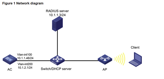
topology
Configuration Steps
Configuring the AC
1. Configure interfaces on the AC:
# Create VLAN 100 and VLAN-interface 100, and assign an IP address to the VLAN interface. The AC will use this IP address to establish a CAPWAP tunnel with the AP.
<AC> system-view
[AC] vlan 100
[AC-vlan100] quit
[AC] interface vlan-interface 100
[AC-Vlan-interface100] ip address 10.1.1.46 24
[AC-Vlan-interface100] quit
# Create VLAN 200 and VLAN-interface 200, and assign an IP address to the VLAN interface. VLAN 200 will be used for client access.
[AC] vlan 200
[AC-vlan200] quit
[AC] interface vlan-interface 200
[AC-Vlan-interface200] ip address 10.1.2.1 24
[AC-Vlan-interface200] quit
2. Configure the LDAP scheme:
# Create an LDAP server named ldap and enter its view.
[AC] ldap server ldap
# Specify the administrator DN.
[AC-ldap-server-ldap] login-dn cn=administrator,cn=users,dc=ldap,dc=com
# Specify the base DN for user search.
[AC-ldap-server-ldap] search-base-dn dc=ldap,dc=com
# Specify the IP address of the LDAP server.
[AC-ldap-server-ldap] ip 10.1.1.3
# Specify the administrator password.
[AC-ldap-server-ldap] login-password simple 123456
[AC-ldap-server-ldap] quit
# Create an LDAP scheme named ldap and enter its view.
[AC] ldap scheme ldap
# Specify ldap as the LDAP authentication server.
[AC-ldap-ldap] authentication-server ldap
[AC-ldap-ldap] quit
# Create an ISP domain named ldap and enter its view.
[AC] domain ldap
# Configure the authentication method as LDAP and the authentication and accounting methods as none for portal users in ISP domain ldap.
[AC-isp-ldap]authentication lan-access ldap-scheme ldap
[AC-isp-ldap] authorization lan-access none
[AC-isp-ldap] accounting lan-access none
# Configure the idle cut feature for users in ISP domain ldap. Log out a user if the user's traffic is less than 1024 bytes in 15 minutes.
[AC-isp-ldap] authorization-attribute idle-cut 15 1024
[AC-isp-ldap] quit
3. Configure the AC to use chap to authenticate 802.1X clients.
[AC] dot1x authentication-method chap
4. Configure a wireless service:
# Create a service template named service and enter its view.
[AC] wlan service-template service
# Configure the SSID of the service template as service.
[AC-wlan-st-service] ssid service
# Assign clients coming online through the service template to VLAN 200.
[AC-wlan-st-service] vlan 200
# Set the AKM mode to 802.1X.
[AC-wlan-st-service] akm mode dot1x
# Set the cipher suite to CCMP.
[AC-wlan-st-service] cipher-suite ccmp
# Enable the RSN IE in beacon and probe responses.
[AC-wlan-st-service] security-ie rsn
# Set the authentication mode to 802.1X.
[AC-wlan-st-service] client-security authentication-mode dot1x
# Specify ISP domain ldap for authenticating 802.1X clients.
[AC-wlan-st-service] dot1x domain ldap
# Enable the service template.
[AC-wlan-st-service] service-template enable
[AC-wlan-st-service] quit
5. Configure a manual AP:
# Create a manual AP named office, and specify the AP model and serial ID
[AC] wlan ap office model WA560-WW
[AC-wlan-ap-office] serial-id 219801A1NM8182032235
# Enter the view of radio 1.
[AC-wlan-ap-office] radio 1
# Bind service template service to radio 1, and enable radio1.
[AC-wlan-ap-office-radio-1] service-template service
[AC-wlan-ap-office-radio-1] radio enable
[AC-wlan-ap-office-radio-1] quit
[AC-wlan-ap-office] quit
Configuring the switch
# Create VLAN 100. The switch will use this VLAN to forward the traffic on the CAPWAP tunnel between the AC and AP.
<Switch> system-view
[Switch] vlan 100
[Switch-vlan100] quit
# Create VLAN 200. The switch will use this VLAN to forward packets for wireless clients.
[Switch] vlan 200
[Switch-vlan200] quit
# Configure GigabitEthernet 1/0/1 (port that connects the switch and the AC) as a trunk port, and assign the trunk port to VLANs 100 and 200.
[Switch] interface gigabitethernet 1/0/1
[Switch-GigabitEthernet1/0/1] port link-type trunk
[Switch-GigabitEthernet1/0/1] port trunk permit vlan 100 200
[Switch-GigabitEthernet1/0/1] quit
# Configure GigabitEthernet 1/0/2 (port that connects the switch and the AP) as an access port, and assign the port to VLAN 100.
[Switch] interface gigabitethernet 1/0/2
[Switch-GigabitEthernet1/0/2] port link-type access
[Switch-GigabitEthernet1/0/2] port access vlan 100
# Enable PoE on GigabitEthernet 1/0/2.
[Switch-GigabitEthernet1/0/2] poe enable
[Switch-GigabitEthernet1/0/2] quit
# Create VLAN-interface 100, and assign an IP address to the VLAN interface.
[Switch] interface vlan-interface 100
[Switch-Vlan-interface100] ip address 10.1.1.47 24
[Switch-Vlan-interface100] quit
# Create VLAN-interface 200, and assign an IP address to the VLAN interface.
[Switch] interface vlan-interface 200
[Switch-Vlan-interface200] ip address 10.1.2.2 24
[Switch-Vlan-interface200] quit
# Configure DHCP pool 100 to assign an IP address to the AP.
[Switch] dhcp server ip-pool 100
[Switch-dhcp-pool-100] network 10.1.1.0 mask 255.255.255.0
[Switch-dhcp-pool-100] gateway-list 10.1.1.46
[Switch-dhcp-pool-100] quit
# Configure DHCP pool 200 to assign an IP address to the client.
[Switch] dhcp server ip-pool 200
[Switch-dhcp-pool-200] network 10.1.2.0 mask 255.255.255.0
[Switch-dhcp-pool-200] gateway-list 10.1.2.1
[Switch-dhcp-pool-200] quit
# Enable DHCP.
[Switch] dhcp enable
Configuring the LDAP server
This example uses Microsoft Windows 2003 Server Active Directory to illustrate the configuration on the LDAP server.
1. Add a user named aaa.
a. On the LDAP server, select Start > Control Panel > Administrative Tools.
b. Double-click Active Directory Users and Computers.
The Active Directory Users and Computers window opens.
c. From the navigation tree, click Users under the ***.*** node.
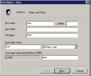
d. Select Action > New > User from the menu to open the dialog box for adding a user.
e. Enter logon name aaa and click Next.
Figure 2 Adding user aaa
f. In the dialog box, enter password 123456, select options as needed, and click Next.
Figure 3 Setting the user's password

g. Click OK.
2. Add user aaa to user group Users:
a. From the navigation tree, click Users under the ***.*** node.
b. In the right pane, right-click user aaa and select Properties.
c. In the dialog box, click the Member Of tab and click Add.
Figure 4 Modifying user properties

d. In the Select Groups dialog box, enter Users in the Enter the object names to select field, and click OK.
User aaa is added to group Users.
Figure 5 Adding user aaa to group Users

3. Configure the administrator password:
a. In the right pane, right-click user Administrator and select Set Password.
b. In the dialog box, enter the administrator password. (Details not shown.)
Verifying the configuration
1. On the client, verify that the client can pass authentication, associate with the AP, and access the wireless network. (Details not shown.)
2. On the AC, perform the following tasks to verify that the user has passed authentication and come online:
# Display detailed WLAN client information.
[AC] display wlan client verbose
Total number of clients: 1
MAC address : 3829-5a40-9589
IPv4 address : N/A
IPv6 address : 2004::4
Username : dot1x
AID : 1
AP ID : 2
AP name : ap1
Radio ID : 1
SSID : service
BSSID : ac74-090a-6421
VLAN ID : 200
Sleep count : 0
Wireless mode : 802.11an
Channel bandwidth : 40MHz
20/40 BSS Coexistence Management : Supported
SM power save : Enabled
SM power save mode : Static
Short GI for 20MHz : Supported
Short GI for 40MHz : Supported
STBC RX capability : Supported
STBC TX capability : Not supported
LDPC RX capability : Not supported
Block Ack : N/A
Supported HT MCS set : 0, 1, 2, 3, 4, 5, 6, 7
Supported rates : 6, 9, 12, 18, 24, 36,
48, 54 Mbps
QoS mode : WMM
Listen interval : 2
RSSI : 0
Rx/Tx rate : 0/0 Mbps
Authentication method : Open system
Security mode : RSN
AKM mode : 802.1X
Cipher suite : CCMP
User authentication mode : 802.1X
Authorization ACL ID : N/A
Authorization user profile : N/A
Roam status : N/A
Key derivation : SHA1
PMF status : N/A
Forwarding policy name : Not configured
Online time : 0days 0hours 0minutes 1seconds
FT status : Inactive
# Display online 802.1X client information.
[AC] display dot1x connection
Total connections: 1
User MAC address : 3829-5a40-9589
AP name : ap1
Radio ID : 1
SSID : service
BSSID : ac74-090a-6421
Username : dot1x
Authentication domain : dom1
IPv6 address : 2004::4
Authentication method : EAP
Initial VLAN : 200
Authorization VLAN : 200
Authorization ACL number : N/A
Authorization user profile : N/A
Termination action : Radius-Request
Session timeout period : 86401 s
Online from : 2018/07/18 10:36:00
Online duration : 0h 0m 19s
Key Configuration
null
No comments
Add Comments:
✖
案例意见反馈


亲~登录后才可以操作哦!
确定你的邮箱还未认证,请认证邮箱或绑定手机后进行当前操作